Parts Assembly Guide
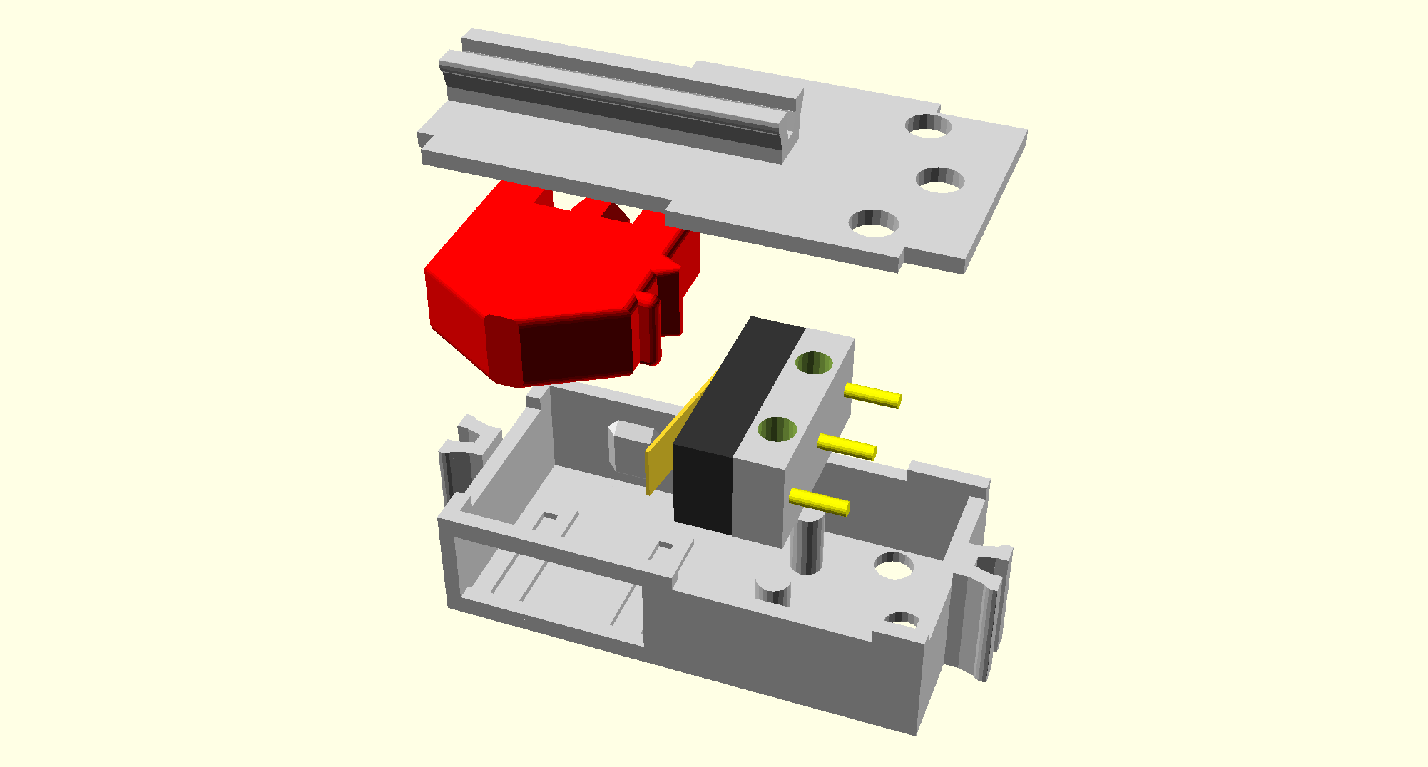
The 2 mini-switches are each assembled from 5 separate parts (including the spring and microswitch). The general assembly is shown in the following diagram:
Two micro-switches are required for the assembly of the mini-switches. The microswitch is a sub-miniature snap action switch from Multicomp, part number DM1-01P-30-3. The datasheet for the microswitch is available here.
Before assembling the microswitch's metal lever must be trimmed so it is as wide as the switch's case when depressed. This will prevent the lever from catching on the outside of the mini-switch's case. Please see the following picture for details (the switch on the left is trimmed, the right switch is the original):

Cut four 40cm wires (these can be trimmed to the correct length later). The wire should be around 24AWG so it easily fits through the holes in the mini-switch case. Two wires should be soldered onto each switch before it is inserted into the mini-switch case. Pay attention to the orientation of the switch in the following picture and which terminals are connected (as the order is important):

The compression spring should be strong enough to ensure the plunger returns easily after being depressed, but also as light as possible so the plunger is easy to depress. The exact length and type of spring will change both the activation pressure and return speed, so it's worth experimenting a little to get the right length based on the spring used.
The spring used in the following picture is a 20mm compression spring with an outer-diameter of 5mm. The spring is cut (using small side-cutters) into thirds as shown below:

Start by fitting the red plunger. Note that the plunger has two guides which fit into the slots provided by the bottom part of the case. The plunger should be inserted at a slight angle and then rotated down into the slots. The plunger should be able to move freely up and down in the slots.
Next insert the microswitch by first threading the wires through the available holes in the mini-switch base. Ensure that the switch lever is pointing in the correct direction (see the picture below).
The compression spring should then be fitted to the base of the plunger. Using a small pair of pliers, ensure that the spring is correctly located onto the holder on the side of the mini-switch base.

Place a small amount of superglue along the recessed parts of the mini-switch bottom case's upper lip as well as a small amount on the top of the microswitch, then insert the top part of the case into the recesses. Press firmly until the glue is set. The finished switch is shown in the following picture:

The block hinge prints in 6 separate parts which require assembly.
First glue the front and back block parts together. Begin by testing the fit to ensure the parts fit firmly together. Then remove the parts, place some superglue in the block front mounting holes then firmly push the back part and front part together. It may be necessary to hold the two parts together lightly in a vice to allow the glue to set.
Next push the two cylinders into the respective top and bottom parts. Add some superglue to the middle of the parts and push the top and bottom assemblies together. Be careful not to use too much glue which will jam the rotational part of the hinge. It may be necessary to hold the two parts together lightly in a vice to allow the glue to set.
Once assembled ensure that the hinge can rotate (the rotation should be quite stiff to hold the hinge in place).

Carefully clear out any remaining support material from the base of the ball caster (use a small flat-ended screwdriver if necessary - be careful of your fingers!). Insert the 20mm steel ball into the base of the ball-caster (the 20mm ball should 'click' into place and not fall out even before the base is attached). Put some superglue in the recess of the ball caster bottom if required (the parts should fit together tightly without glue) and place the bottom piece onto the top piece being careful to align the two parts. The ball caster should fit tightly into the ball caster holder piece (glue shouldn't be necessary, but can be used if required).
