![]()
A personal, progressive FPGA / VHDL (and now Verilog) tutorial — a collection of small self-contained examples that build up from a blinking LED to richer designs (PWM, UART, FIFO, shift registers, 7-segment mux, mini-game, VGA & I²S sketches, plus a tutorial-grade RV32I RISC-V computer: single-cycle + pipelined CPUs, a small SoC with memory-mapped UART and SIMD/DSP accelerators, and a tiny Python assembler — see cpu/README.md).
Every project simulates, renders its netlist diagram (*.svg), and
renders a waveform diagram (*.svg + *.png) of a testbench
simulation automatically in CI. The examples below embed the
latest diagrams and waveforms rendered from main — they update
whenever the source changes.
- 📚 What it is — a tutorial you can read front-to-back, or dip into one example at a time.
- 🪞 Two languages side-by-side — most examples ship in both VHDL and Verilog with matching behaviour.
- 🧪 Reproducible — one
makebuilds everything locally and in CI, through the same pinned container image. - 🤝 Easy to extend — drop a
Makefilein a new directory and CI picks it up (see CONTRIBUTING.md).
Every main CI run publishes its netlist SVGs and waveform SVG/PNGs
inline in every job summary, on the run-summary page, and on PR comments
— see the
latest successful main run.
The same images are mirrored on the
ci-gallery/latest/
branch and embedded in the Gallery below, refreshed on every
main push.

The original target was the RZ EasyFPGA A2.2 (Banggood listing) — an Altera/Intel Cyclone IV EP4CE6E22C8N (datasheet) board, synthesised with Intel Quartus Prime Lite 21.1 (download). The project has since grown more general and is no longer tied to that specific board.
Every diagram / waveform below is the latest output from CI on main
(served from the
ci-gallery branch).
For every project that ships both languages, VHDL is shown on the left
and Verilog on the right so you can compare the two directly.
Tip: click a
<summary>bar to expand each project.
glossary — symbol legend: every primitive on one diagram, with truth tables
| VHDL | Verilog | |
|---|---|---|
glossary (netlist) |
 |
 |
tb_glossary |
 |
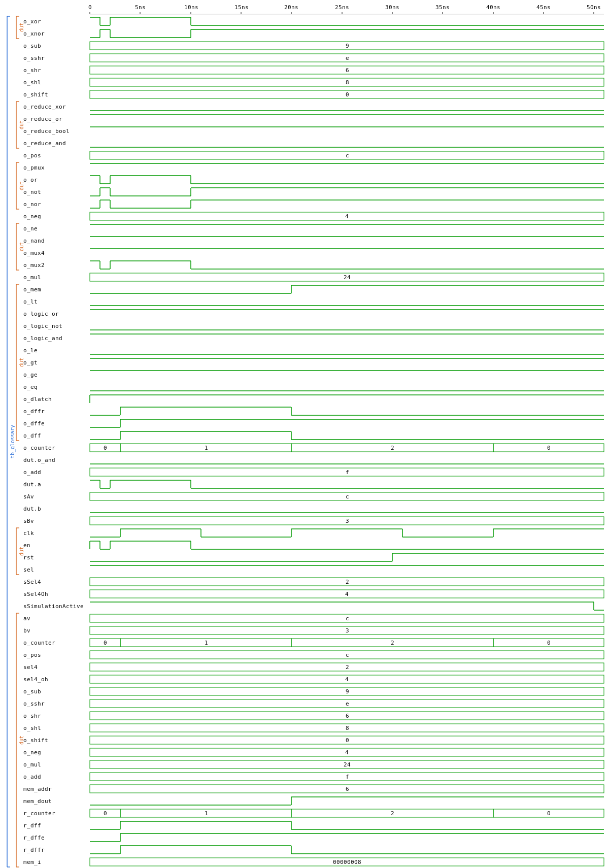 |
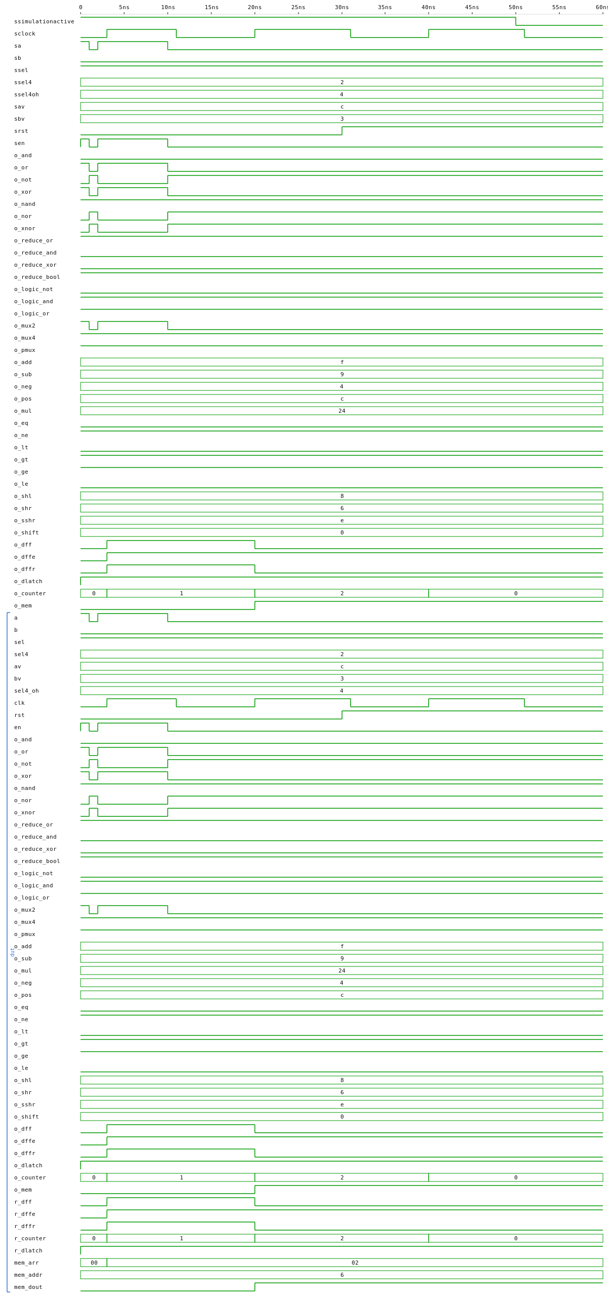
A flat module that drives one output per primitive (bitwise gates, vector reductions, 2:1 / 4:1 muxes, adder / sub, comparators, shifters, plain / enabled / sync-reset D flip-flops, counter) so every cell appears once in the synthesised netlist with no fan-out clutter. The project ships a small custom netlistsvg skin that adds a text label across each IEEE gate shape (AND, OR, NOT, XOR, NAND, NOR, XNOR) so you can map shape ↔ name at a glance and then spot the same symbols in any other diagram below.
Truth tables for every primitive (click to expand)
Bitwise gates (1-bit a, b)
a |
b |
o_and |
o_or |
o_nand |
o_nor |
o_xor |
o_xnor |
|---|---|---|---|---|---|---|---|
| 0 | 0 | 0 | 0 | 1 | 1 | 0 | 1 |
| 0 | 1 | 0 | 1 | 1 | 0 | 1 | 0 |
| 1 | 0 | 0 | 1 | 1 | 0 | 1 | 0 |
| 1 | 1 | 1 | 1 | 0 | 0 | 0 | 1 |
a |
o_not |
|---|---|
| 0 | 1 |
| 1 | 0 |
Vector reductions (4-bit av)
reduce_or = av[3] | av[2] | av[1] | av[0] (1 iff any bit is 1) · reduce_and = av[3] & av[2] & av[1] & av[0] (1 iff all bits are 1) · reduce_xor = av[3] ^ av[2] ^ av[1] ^ av[0] (1 iff an odd number of bits is 1 — parity).
av |
o_reduce_or |
o_reduce_and |
o_reduce_xor |
|---|---|---|---|
0000 |
0 | 0 | 0 |
0001 |
1 | 0 | 1 |
1010 |
1 | 0 | 0 |
1100 |
1 | 0 | 0 |
1101 |
1 | 0 | 1 |
1111 |
1 | 1 | 0 |
Multiplexers
sel |
o_mux2 |
sel4 |
o_mux4 |
|
|---|---|---|---|---|
| 0 | b |
00 |
av[0] |
|
| 1 | a |
01 |
av[1] |
|
10 |
av[2] |
|||
11 |
av[3] |
Arithmetic, comparators, shifts (4-bit operands, mod-16 wrap; example column uses av = 1100 (12), bv = 0011 (3))
| Output | Definition | Example |
|---|---|---|
o_add |
(av + bv) mod 16 |
1100 + 0011 = 1111 (12+3 = 15) |
o_sub |
(av - bv) mod 16 |
1100 - 0011 = 1001 (12-3 = 9) |
o_eq |
1 iff av == bv |
0 (12 ≠ 3) |
o_lt |
1 iff av < bv (unsigned) |
0 (12 ≥ 3) |
o_shl |
av << 1, MSB shifted out, LSB ← 0 |
1100 << 1 = 1000 |
o_shr |
av >> 1, LSB shifted out, MSB ← 0 |
1100 >> 1 = 0110 |
Sequential cells (Q_next is the value the register takes at the next rising edge of clk; outside a rising edge it simply holds)
| Cell | clk |
en |
rst |
a |
Q_next |
|---|---|---|---|---|---|
dff |
↑ | — | — | 0 | 0 |
dff |
↑ | — | — | 1 | 1 |
dff_en |
↑ | 0 | — | x | hold |
dff_en |
↑ | 1 | — | a | a |
dff_rst |
↑ | — | 1 | x | 0 |
dff_rst |
↑ | — | 0 | a | a |
counter4 |
↑ | — | 1 | — | 0000 |
counter4 |
↑ | — | 0 | — | Q + 1 (mod 16) |
logic_styles — coding-style tutorial: combinational vs. sequential vs. latch, register-init strategies, the latch trap
| VHDL | Verilog | |
|---|---|---|
logic_styles (netlist) |
 |
 |
tb_logic_styles |
 |
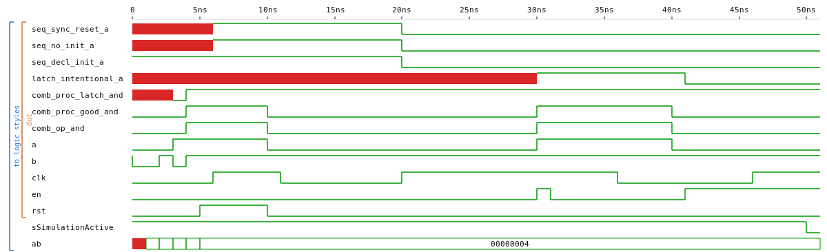 |
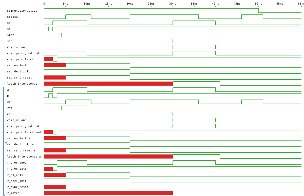
A small companion to glossary that focuses on how the cell got there rather than which gate it is. The same module surfaces three families — combinational (good and broken), sequential (three init strategies side-by-side: no-init, declaration-init, explicit reset), and an intentional level-sensitive latch — so the netlist diagram shows them all next to each other ($and, three $dff, two $dlatch). The board top wires the latch trap onto LED1 and a real transparent latch onto LED3 so the holding behaviour is visible by hand. The testbench reads each register at t=1 ns before the first clock edge to make the init-style differences observable as 'U' / '1' / 'U'.
blink_led — the "hello world", in two variants: 1-FF minimal vs. 2-FF exact-period
Two designs that do almost the same thing but synthesise to clearly different netlists. blink_led_minimal is the absolute minimum (counter + wire to its top bit, period fixed to a power of two); blink_led adds a second flip-flop that toggles on counter wrap so the period is exactly CLOCKS_TO_OVERFLOW cycles. Read the source side by side to see what each line costs in cells.
| VHDL | Verilog | |
|---|---|---|
blink_led_minimal (netlist, 1 FF) |
 |
 |
blink_led (netlist, 2 FF, exact period) |
 |
 |
tb_blink_led |
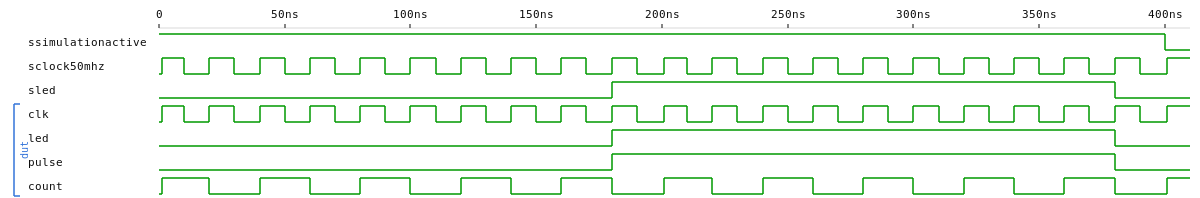 |
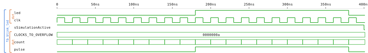 |
tb_blink_led_minimal |
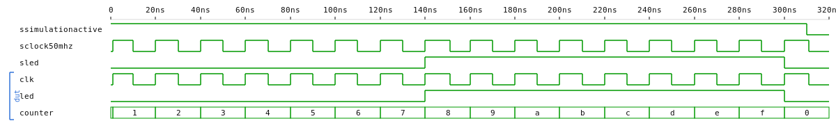 |
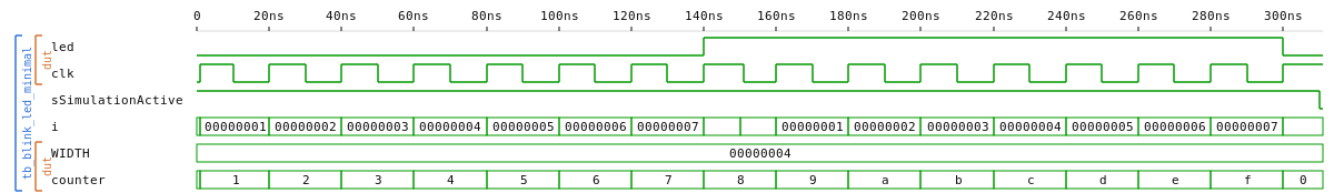 |
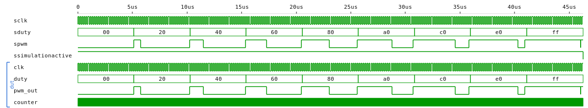
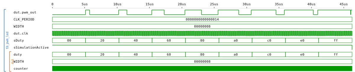
pwm_led — duty-cycle modulation driving an LED
| VHDL | Verilog | |
|---|---|---|
pwm_led (netlist) |
 |
 |
tb_pwm_led |
 |
 |
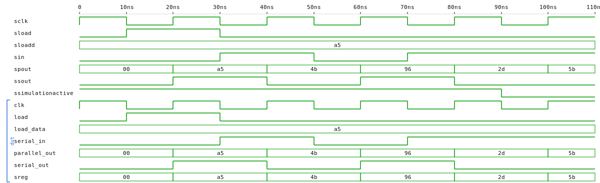
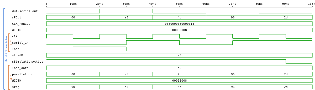
shift_register — parameterisable shift register
| VHDL | Verilog | |
|---|---|---|
shift_register (netlist) |
 |
 |
tb_shift_register |
 |
 |
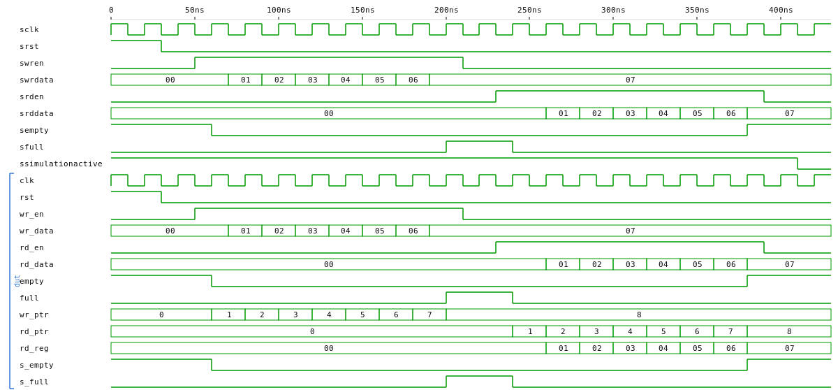
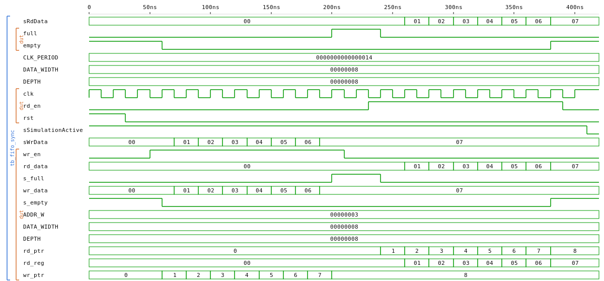
fifo_sync — synchronous FIFO with full / empty flags
| VHDL | Verilog | |
|---|---|---|
fifo_sync (netlist) |
 |
 |
tb_fifo_sync |
 |
 |
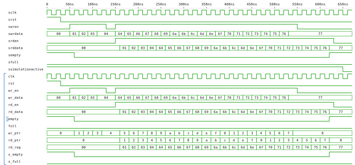
tb_fifo_sync_overlapping |
 |
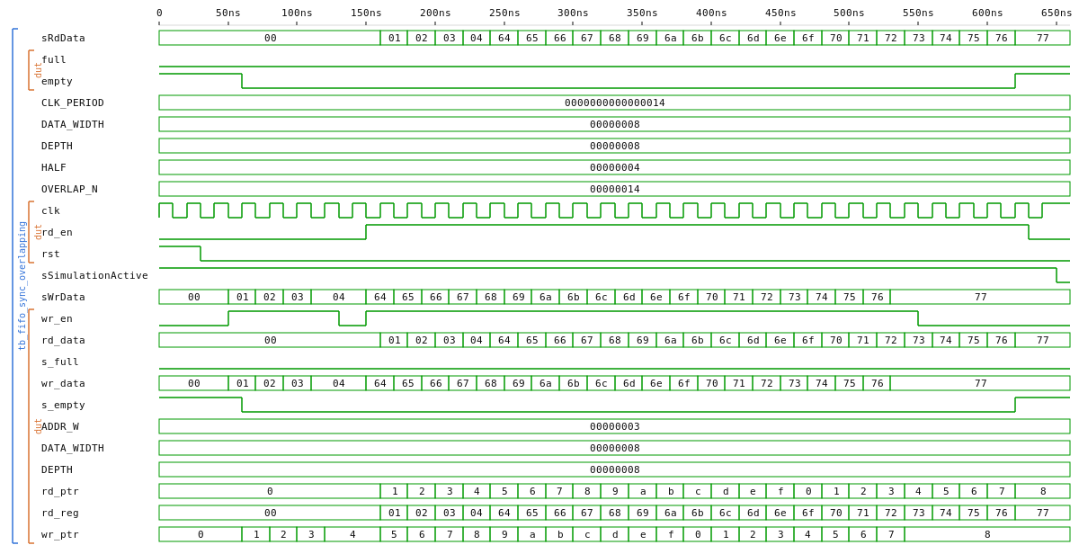 |
Two testbenches each side: tb_fifo_sync covers full-fill/drain/ordering, tb_fifo_sync_overlapping covers the simultaneous read+write case (occupancy invariance + ordering under overlap).
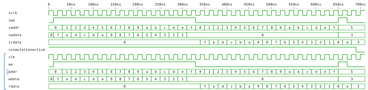
ram_sync — generic single-port synchronous BRAM with optional hex-file init
| VHDL | Verilog | |
|---|---|---|
ram_sync (netlist) |
 |
 |
tb_ram_sync |
 |
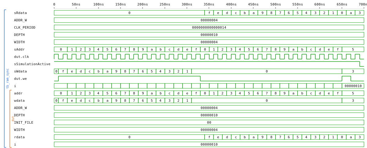 |
Parameterised width / depth; the address-width generic with DEPTH = 2**ADDR_W derived inside the architecture (avoids ieee.math_real/$clog2 in the port list for cross-tool portability — same idiom as fifo_sync). The VHDL twin uses the signal-not-constant BRAM-inference quirk so Quartus actually maps it to a block RAM (see ROM_LUT.vhd for the original example). Used as IMEM and DMEM in the RV32I CPU + SoC.
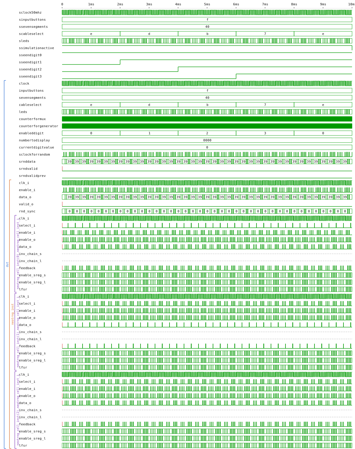
random_generator — on-chip random number generator, viewed on a 4-digit 7-segment
| VHDL | Verilog | |
|---|---|---|
random_generator (netlist) |
 |
 |
tb_random_generator (10 ms) |
 |
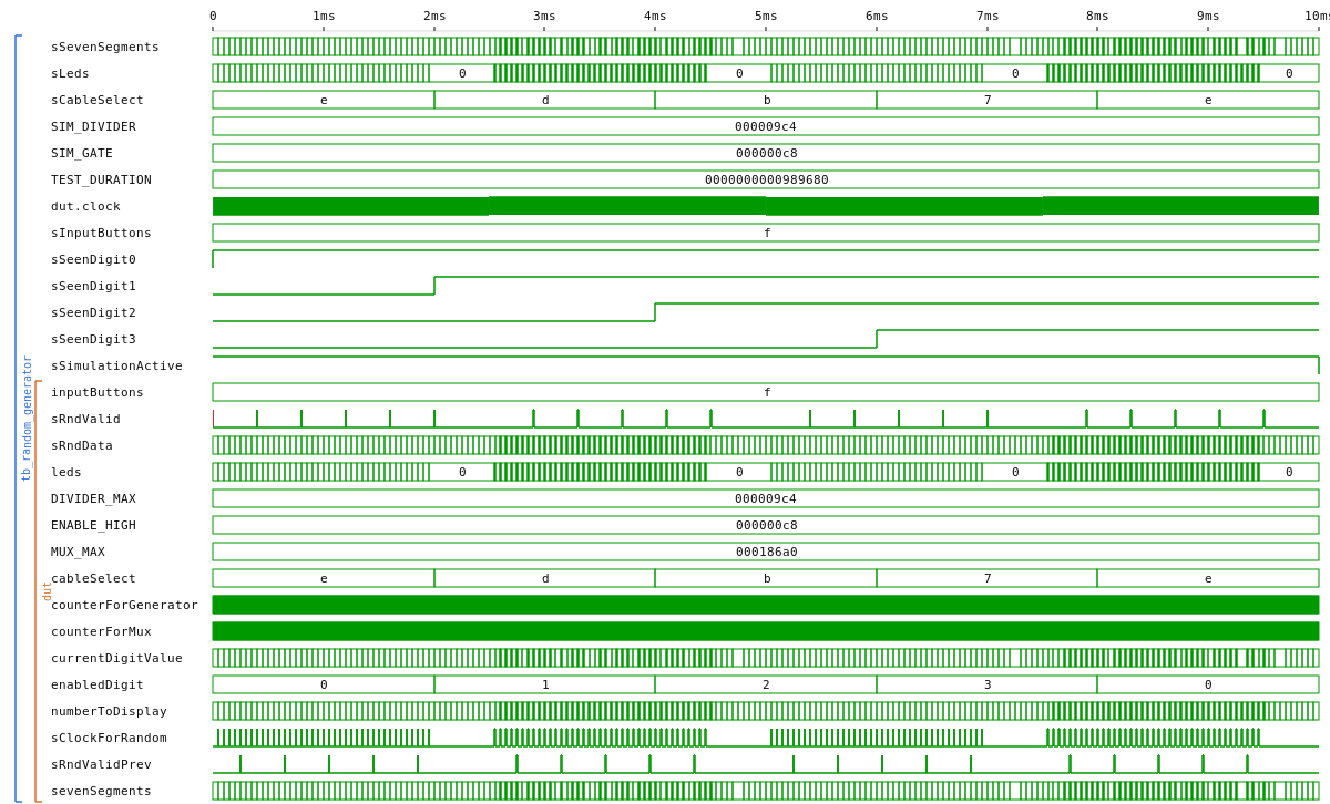 |
The two language sides use different random sources: VHDL drives neoTRNG (chaotic ring oscillators on hardware, internal LFSR fallback for sim, gated by the IS_SIM generic); Verilog drives a small Galois LFSR (lfsr.v) in both flows. inputButtons[0] freezes the displayed value. A second testbench tb_random_generator_long (12 ms) asserts both update-on-release and freeze-on-press.
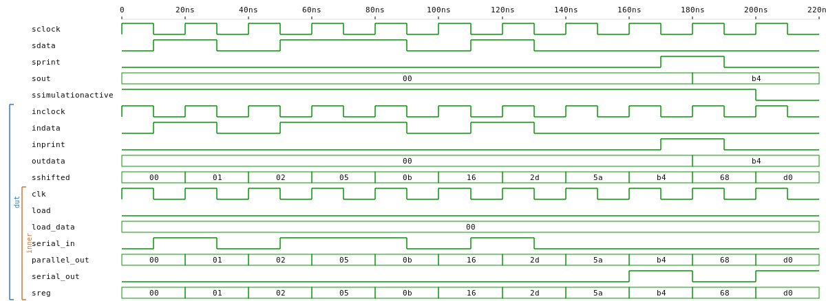
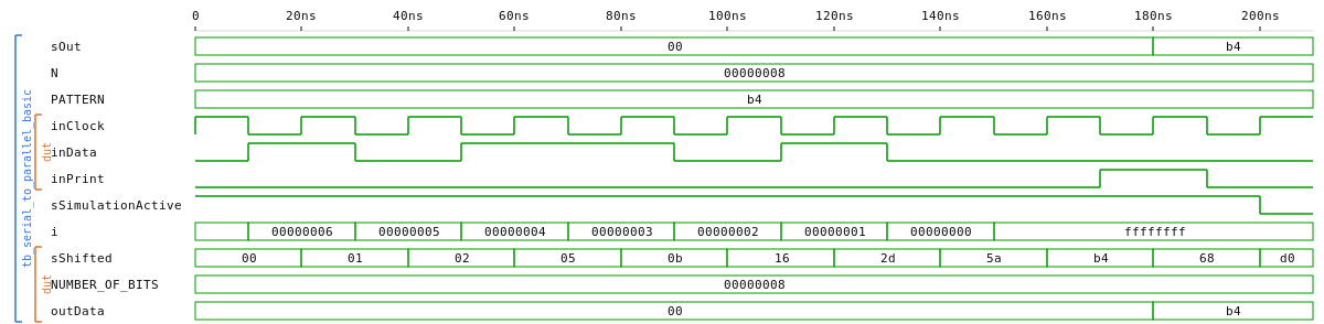
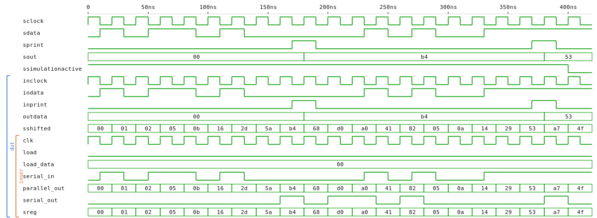
serial_to_parallel — SIPO shift + snapshot register; wrapper around shift_register
| VHDL | Verilog | |
|---|---|---|
Serial2Parallel (netlist) |
 |
 |
tb_serial_to_parallel_basic |
 |
 |
tb_serial_to_parallel_print_gating |
 |
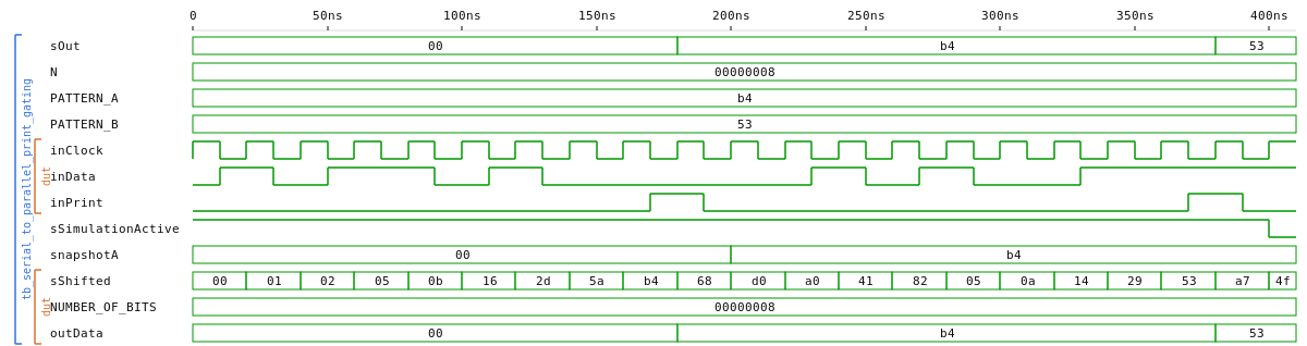 |
Two focused testbenches: tb_serial_to_parallel_basic shifts in 0xB4 MSB-first, pulses inPrint, and asserts the latched outData; tb_serial_to_parallel_print_gating checks that the snapshot register actually gates — outData stays at its initial value while inPrint=0, latches on the first pulse, then survives a second wave of shifting before re-latching on the second pulse.
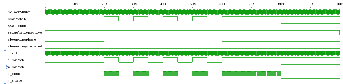
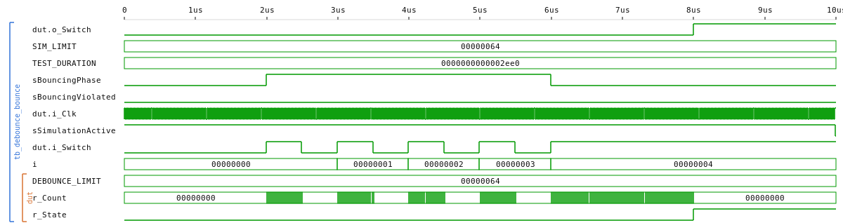
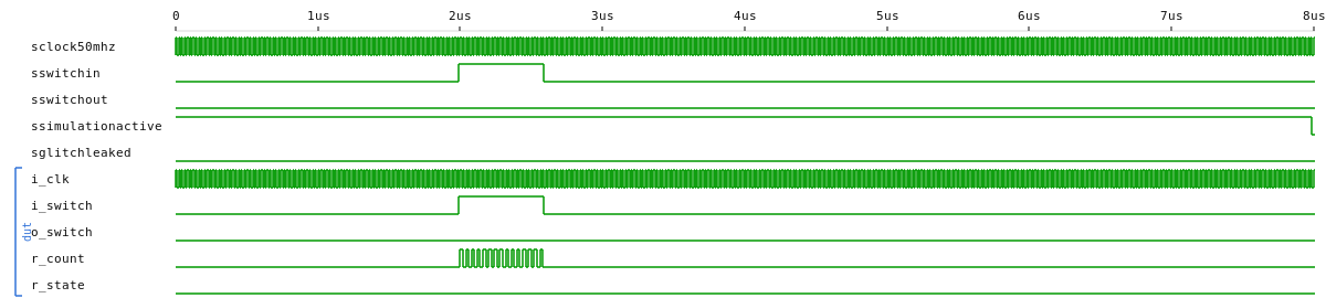
debounce — switch / button debouncer
| VHDL | Verilog | |
|---|---|---|
Debounce (netlist) |
 |
 |
tb_debounce_bounce |
 |
 |
tb_debounce_glitch |
 |
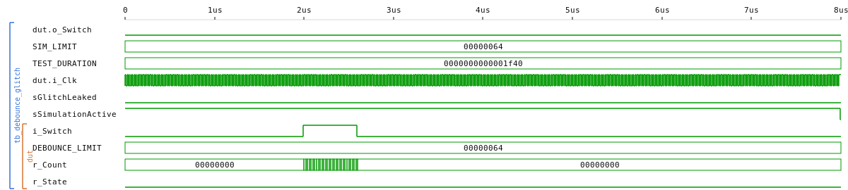 |
DEBOUNCE_LIMIT is overridden in both testbenches to 100 cycles (2 µs) so the wait window fits in a short sim. tb_debounce_bounce drives a bouncing input that settles high — output must stay 0 while bouncing, then propagate to 1 once steady. tb_debounce_glitch drives a single sub-limit pulse — output must stay 0.
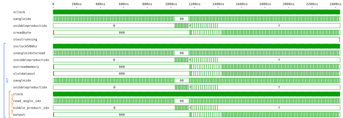
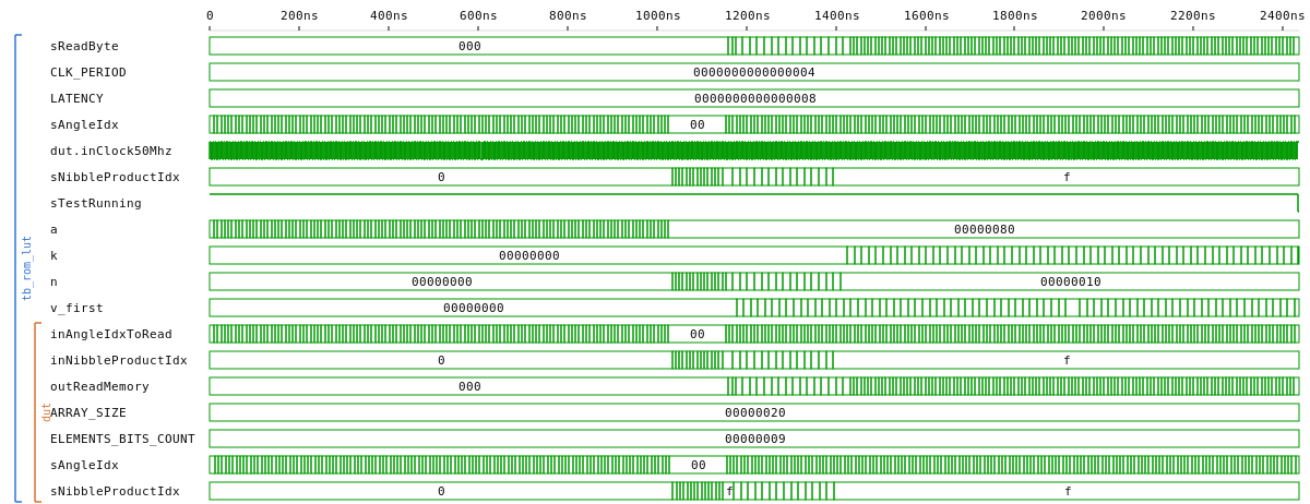
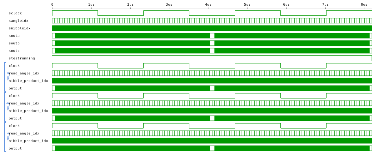
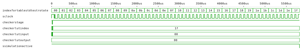
rom_lut — same lookup table, three storage methods (inline literal, external hex file, computed at elaboration)
| VHDL | Verilog | |
|---|---|---|
tl_rom_lut (netlist) |
 |
 |
tb_rom_lut |
 |
 |
tb_rom_lut_methods |
 |
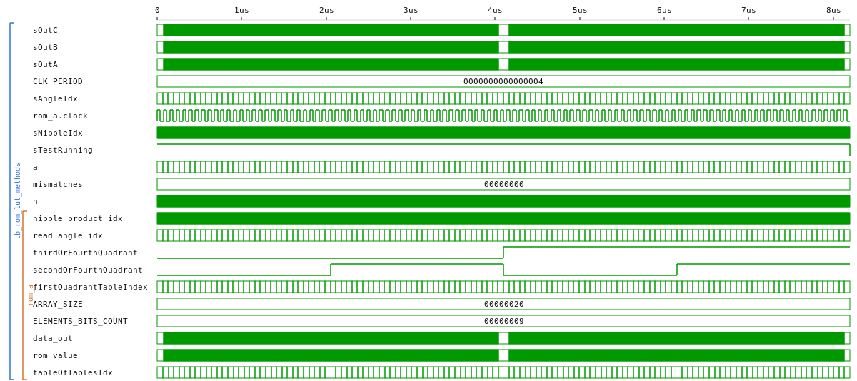 |
A 32 × 16 ROM of precomputed sin(angle) × nibble values for the first quadrant; the wrapping logic mirrors around π/2 and negates across π so a 7-bit angle index covers the full circle. The interesting part is the multi-method demo: the same table is populated three different ways — inline literal, external hex file (textio / $readmemh), and computed at elaboration from IEEE.MATH_REAL / $sin — and a dedicated testbench (tb_rom_lut_methods) drives all three implementations in parallel and asserts bit-identical outputs across the entire 2048-address space. The synthesised TOP wraps method A (inline); methods B and C live alongside as simulation-time alternatives.
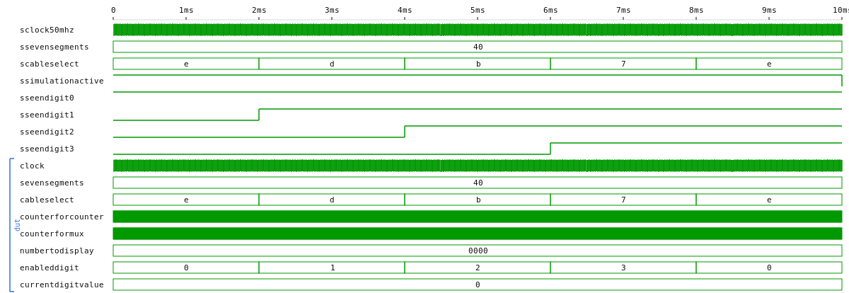
7segments/counter — multiplexed 4-digit counter
| VHDL | Verilog | |
|---|---|---|
counter (netlist) |
 |
 |
tb_counter (10 ms) |
 |
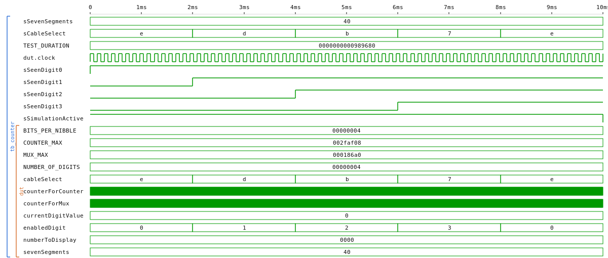 |
A second testbench tb_counter_long (150 ms) runs in CI asserting the internal counter ticks, but dumps FST without a rendered waveform (at that zoom level the 20 ns clock period is sub-pixel anyway).
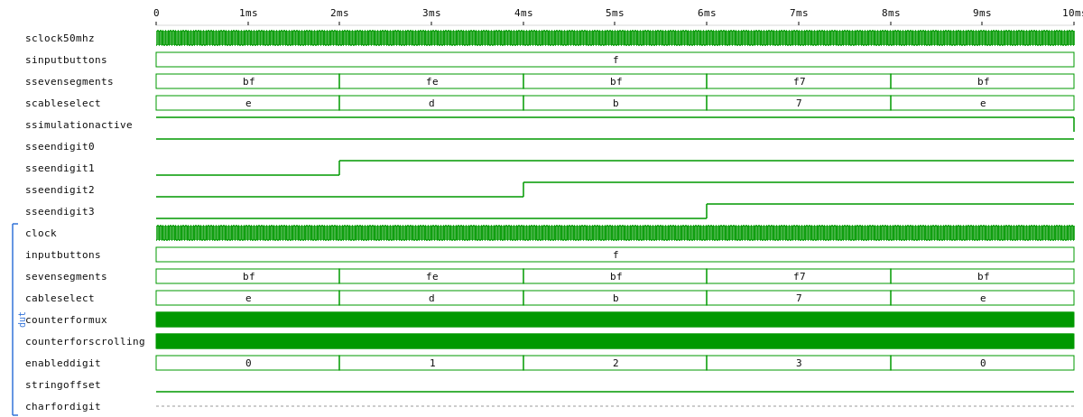
7segments/text — scrolling ASCII text on a 4-digit display
| VHDL | Verilog | |
|---|---|---|
text (netlist) |
 |
 |
tb_text (10 ms) |
 |
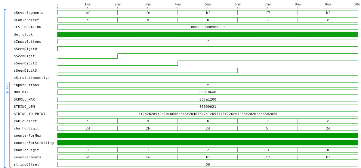 |
inputButtons[0] is wired as an active-low scroll-pause; sevenSegments[7] is the decimal point. A second testbench tb_text_long (40 ms) compresses the scroll period via the SCROLL_MAX generic and asserts both that the scroll advances when the button is released and that it freezes when the button is held; dumps FST without a rendered waveform.
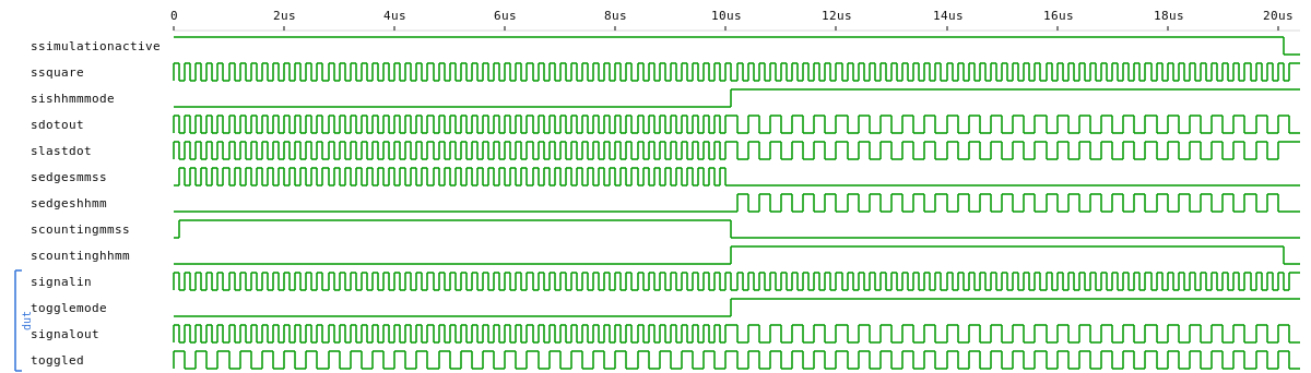
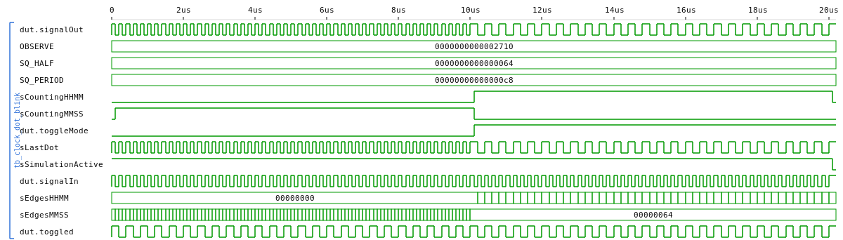
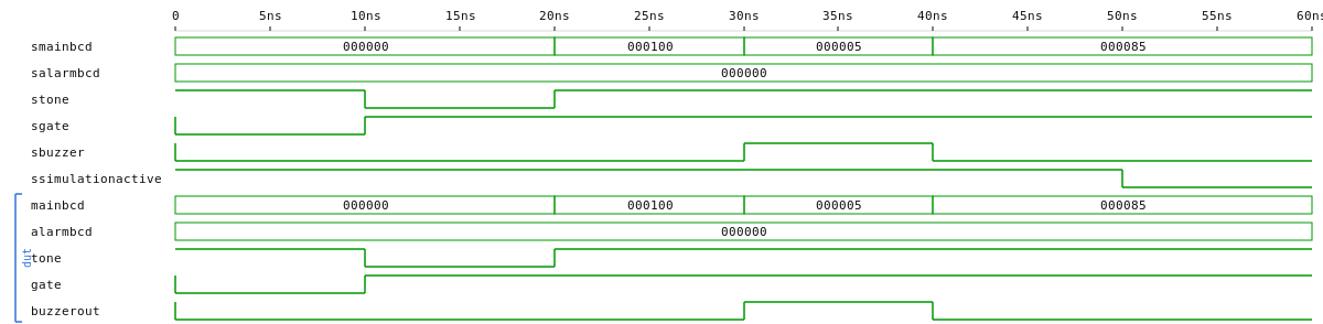
7segments/clock — multiplexed clock with HHMM/MMSS view, blinking dot, alarm
| VHDL | Verilog | |
|---|---|---|
top_level_7segments_clock (netlist) |
 |
 |
tb_clock_dot_blink |
 |
 |
tb_clock_alarm |
 |
 |
The two testbenches target the salvaged-from-2022 features as standalone entities: tb_clock_dot_blink asserts the 2:1 toggle ratio between MMSS and HHMM views (cause-effect on isHHMMMode); tb_clock_alarm covers the four match/mismatch × tone/gate combinations and the immediate-low transition when the match breaks. Both flows ship a complete top-to-bottom mirror — every VHDL leaf has a matching Verilog file, the two top-level netlist diagrams render side by side, and the testbenches assert identical properties on each language.
vga_sprites — VGA sprite demo with trigonometric rotation + optional gravity
| VHDL | Verilog | |
|---|---|---|
sprite (netlist) |
||
tb_trigonometric |
 |
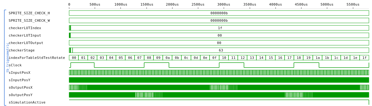 |
tb_multiply_by_sin_lut |
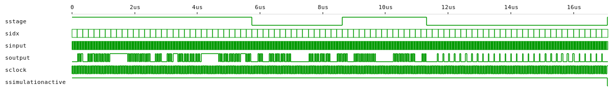 |
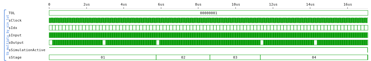 |
tb_sprite_gravity |
Three focused testbenches: tb_trigonometric (integration sweep + rotate properties), tb_multiply_by_sin_lut (LUT unit tests — odd symmetry, anti-symmetry across π, mirror across π/2, magnitude bound), tb_sprite_gravity (sprite entity with gravity on — fall/bounce cause-effect check). VHDL and Verilog twins simulate the same sin/cos LUT and rotate() math; the trig functions live in trigonometric_functions.vh and are \include`d into each module that needs them.
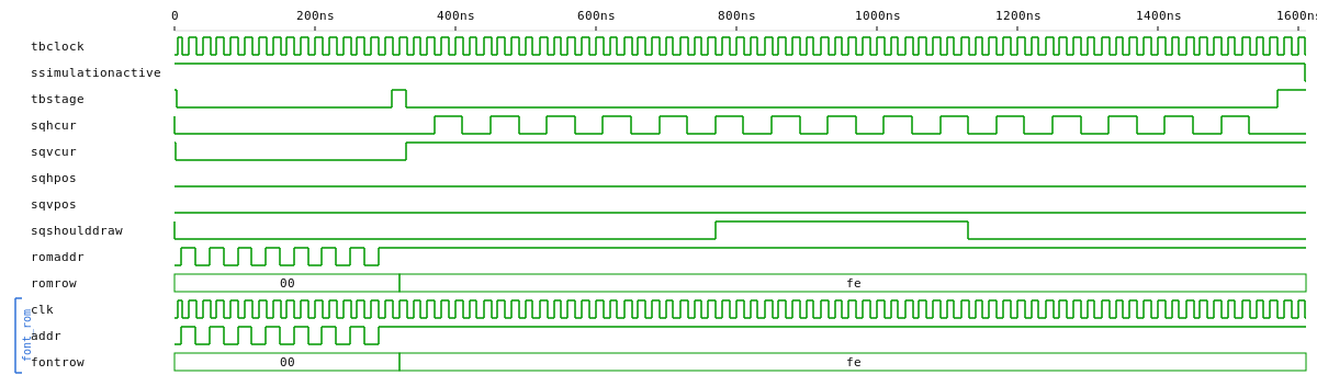
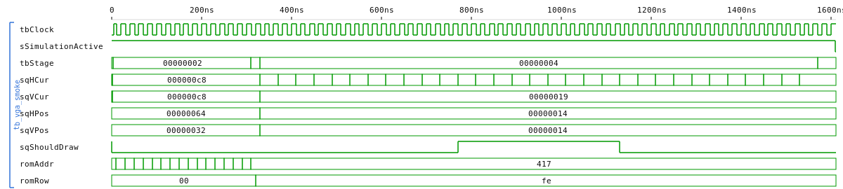
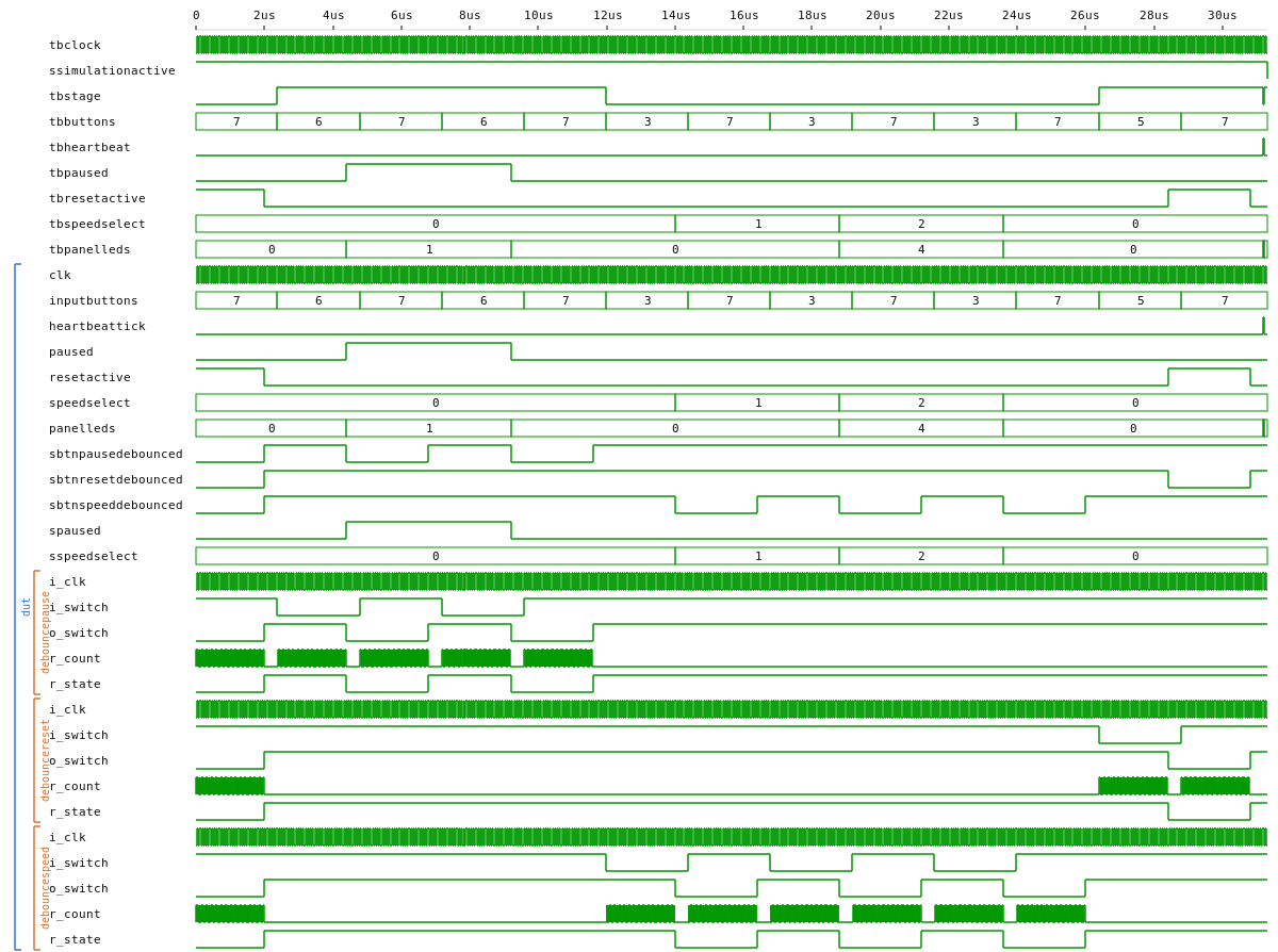
vga — bouncing square + scrolling text demo, with debounced pause/reset/speed buttons and status LEDs
| VHDL | Verilog | |
|---|---|---|
VgaController (netlist) |
 |
 |
tb_vga_smoke |
 |
 |
tb_vga_top |
 |
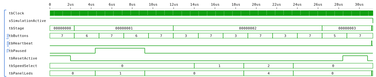 |
Both flows synth the same VgaController timing FSM (vga_driver/VgaController.vhd ↔ vga_driver/vga_controller.v, both ported from fsmiamoto/EasyFPGA-VGA); the full top_level_vga_test is GHDL-analysed but not in either diagram because its string-typed generics on Pixel_On_Text* aren't synthesisable by yosys+ghdl-plugin. Two testbenches: tb_vga_smoke covers the Square strict-less-than box test plus Font_Rom NUL-glyph + 'A' row-7 reads. tb_vga_top exercises the control_panel building block — three debouncers + pause toggle + speed cycler + LED panel — that the top instantiates: it walks the pause flag 0 → 1 → 0, the speed selector medium → slow → fast → medium, the reset level high then low, and the heartbeat passthrough. Both testbenches ship VHDL + Verilog twins through control_panel.{vhd,v}.
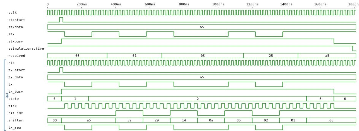
uart_tx — a minimal 8N1 UART transmitter
| VHDL | Verilog | |
|---|---|---|
uart_tx (netlist) |
 |
 |
tb_uart_tx |
 |
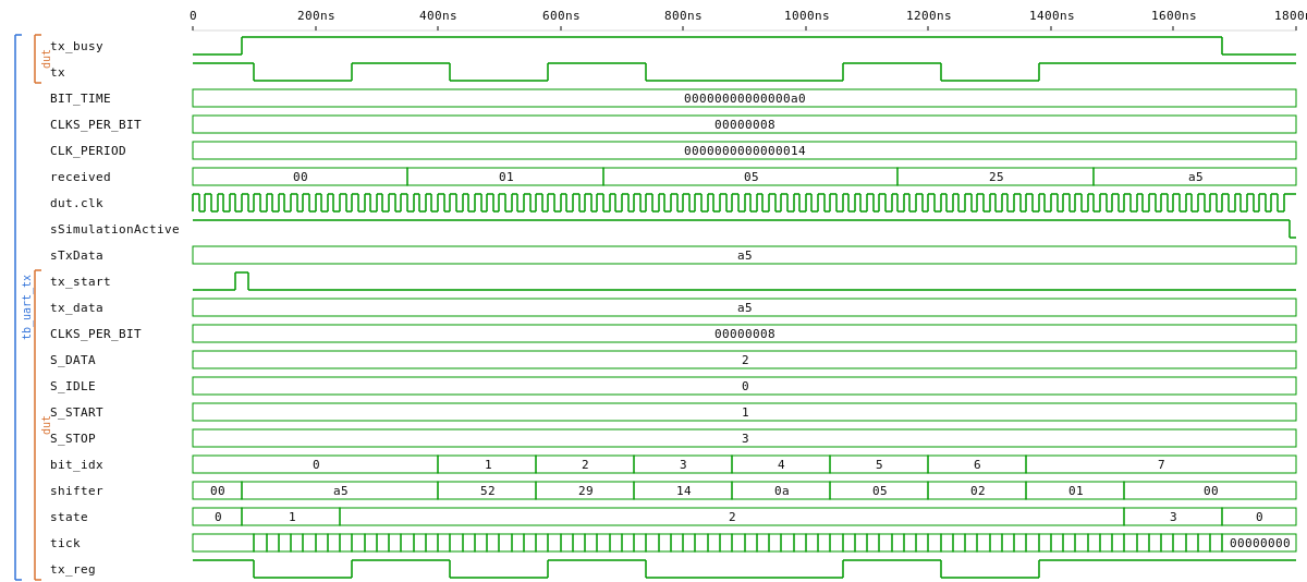 |
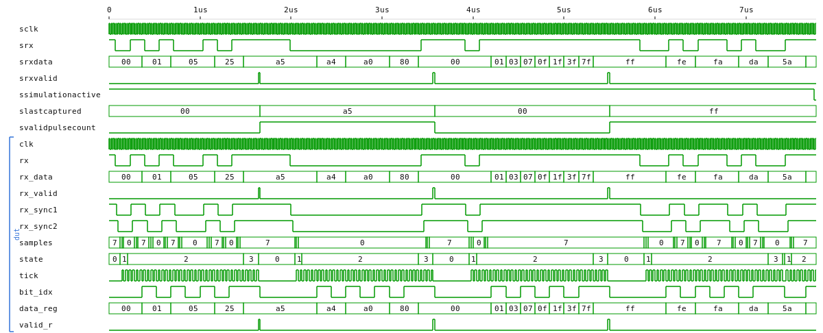
uart_rx — 8N1 UART receiver, 3-tap majority sampler at mid-bit (pairs with uart_tx)
| VHDL | Verilog | |
|---|---|---|
uart_rx (netlist) |
 |
 |
tb_uart_rx |
 |
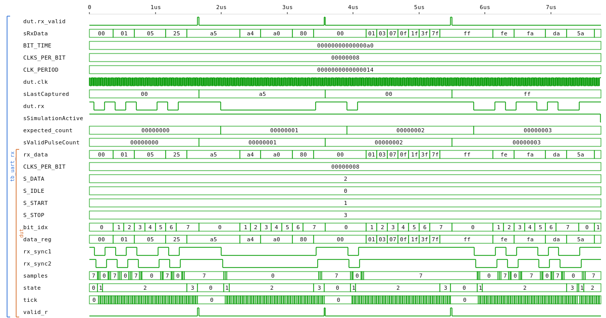 |
Same CLKS_PER_BIT generic as uart_tx (default 5208 for 50 MHz / 9600 baud). The receiver oversamples each bit at the centre with a 3-tap majority vote, so a single-cycle glitch on the line doesn't corrupt the captured byte. Used by cpu/riscv_soc's memory-mapped UART_RX peripheral.
See cpu/README.md for the tutorial overview — recommended reading order, RV32I subset reference, SoC MMIO map, and how to write+assemble+run your own program.
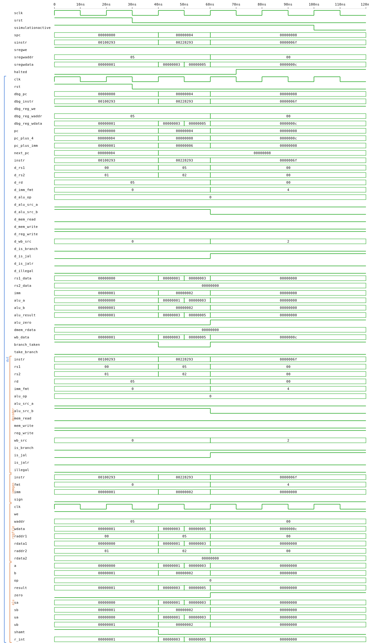
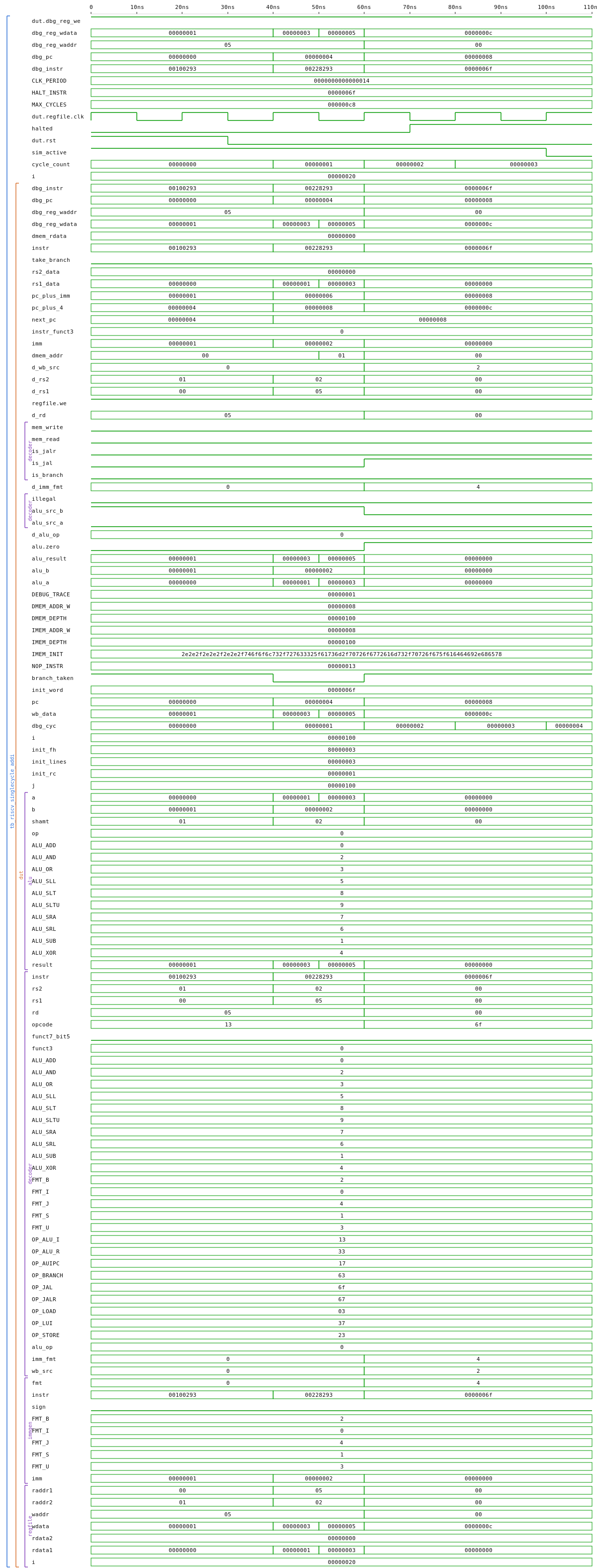
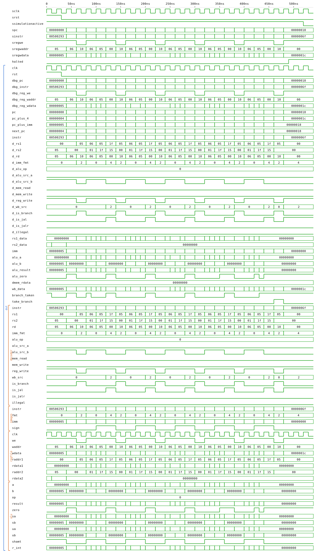
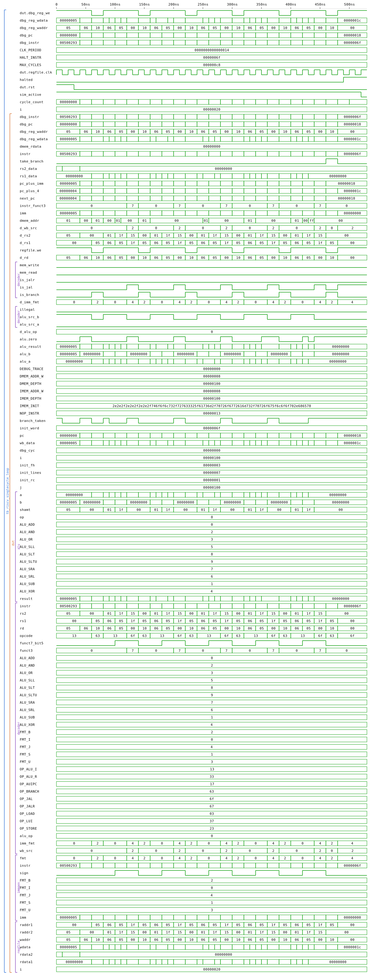
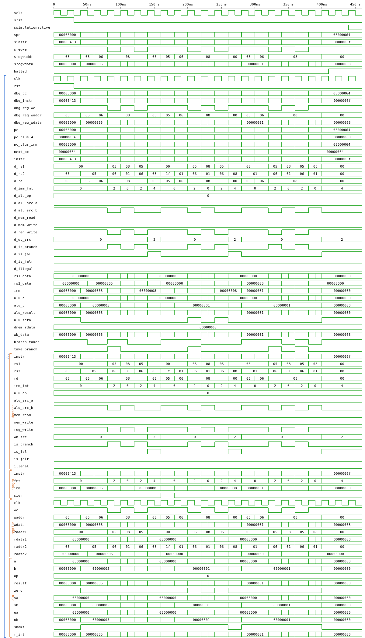
riscv_singlecycle — textbook single-cycle RV32I CPU; one instruction per clock, no pipeline registers
| VHDL | Verilog | |
|---|---|---|
riscv_singlecycle (netlist) |
 |
 |
tb_riscv_singlecycle_addi |
 |
 |
tb_riscv_singlecycle_loop |
 |
 |
tb_riscv_singlecycle_branches |
 |
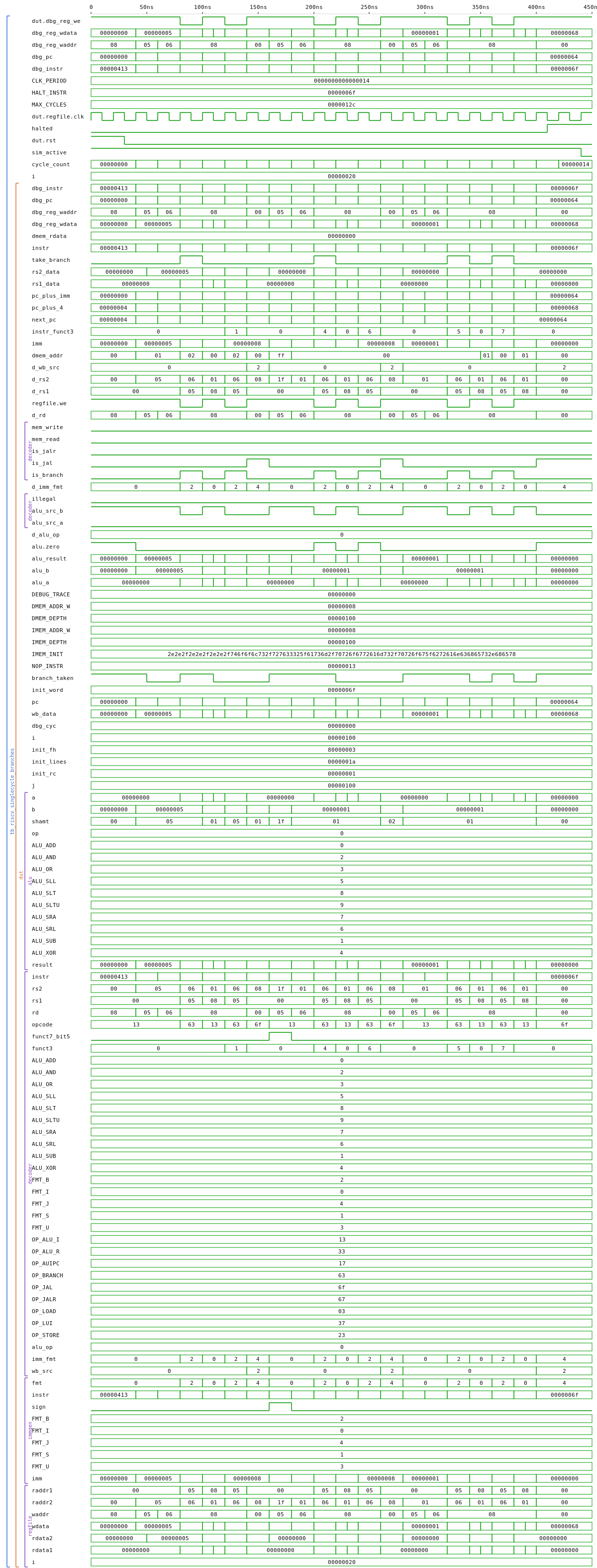 |
Composes structurally from the RV32 building blocks (alu_rv32, regfile_rv32, immgen_rv32, decoder_rv32, ram_sync). Internal IMEM (init from IMEM_INIT hex) + DMEM (sync write / async read). Three programs from tools/rv32_asm/programs/ run end-to-end: prog_addi (basic R/I-type), prog_loop (counted decrement loop with back-edge branch), prog_branches (every branch flavour taken AND not-taken).
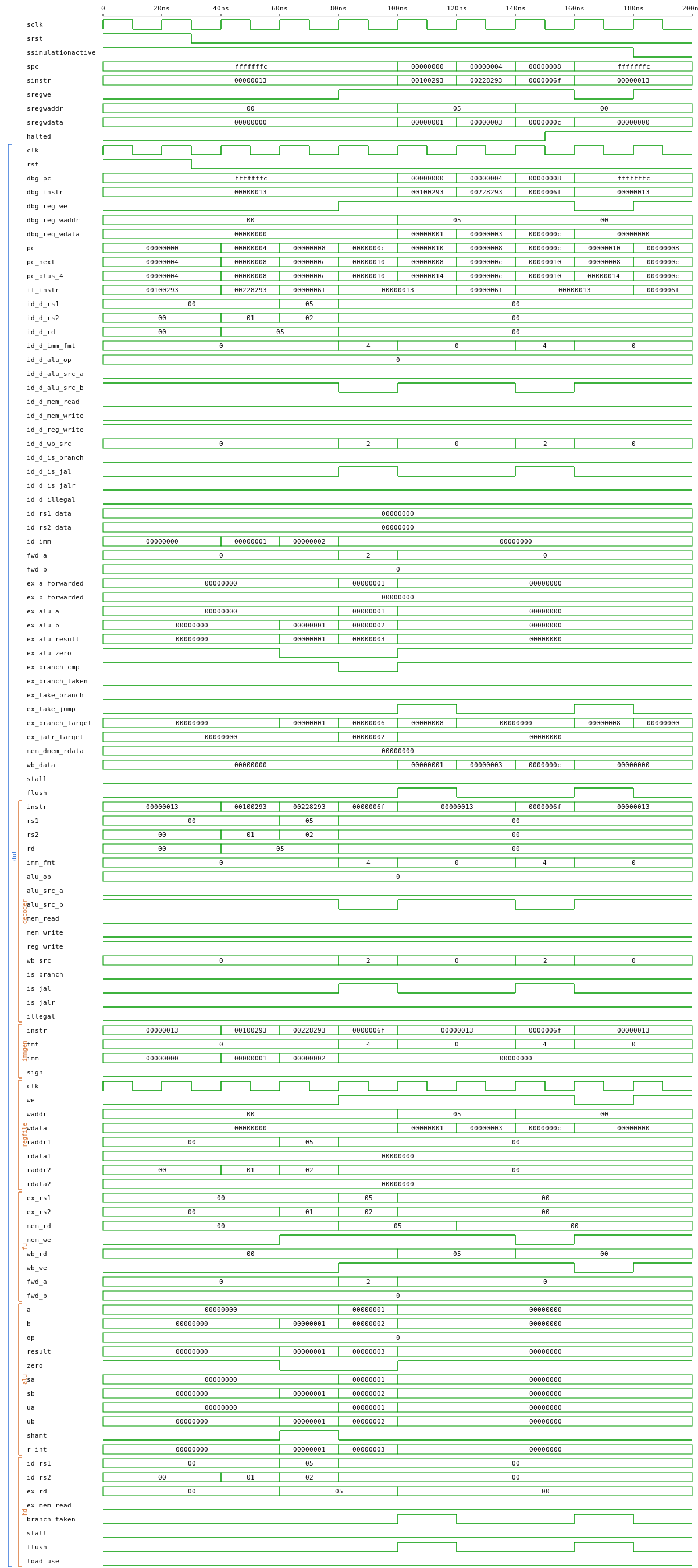
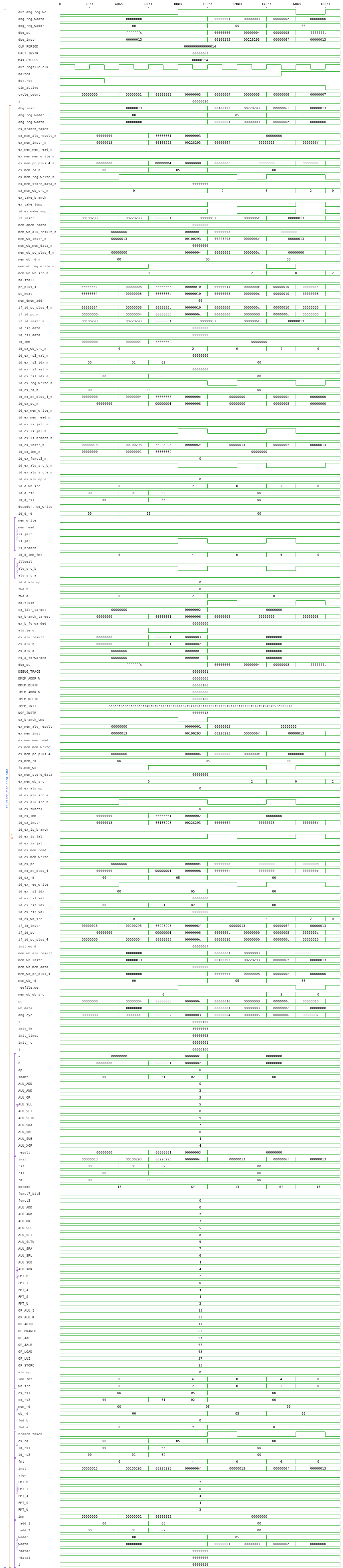
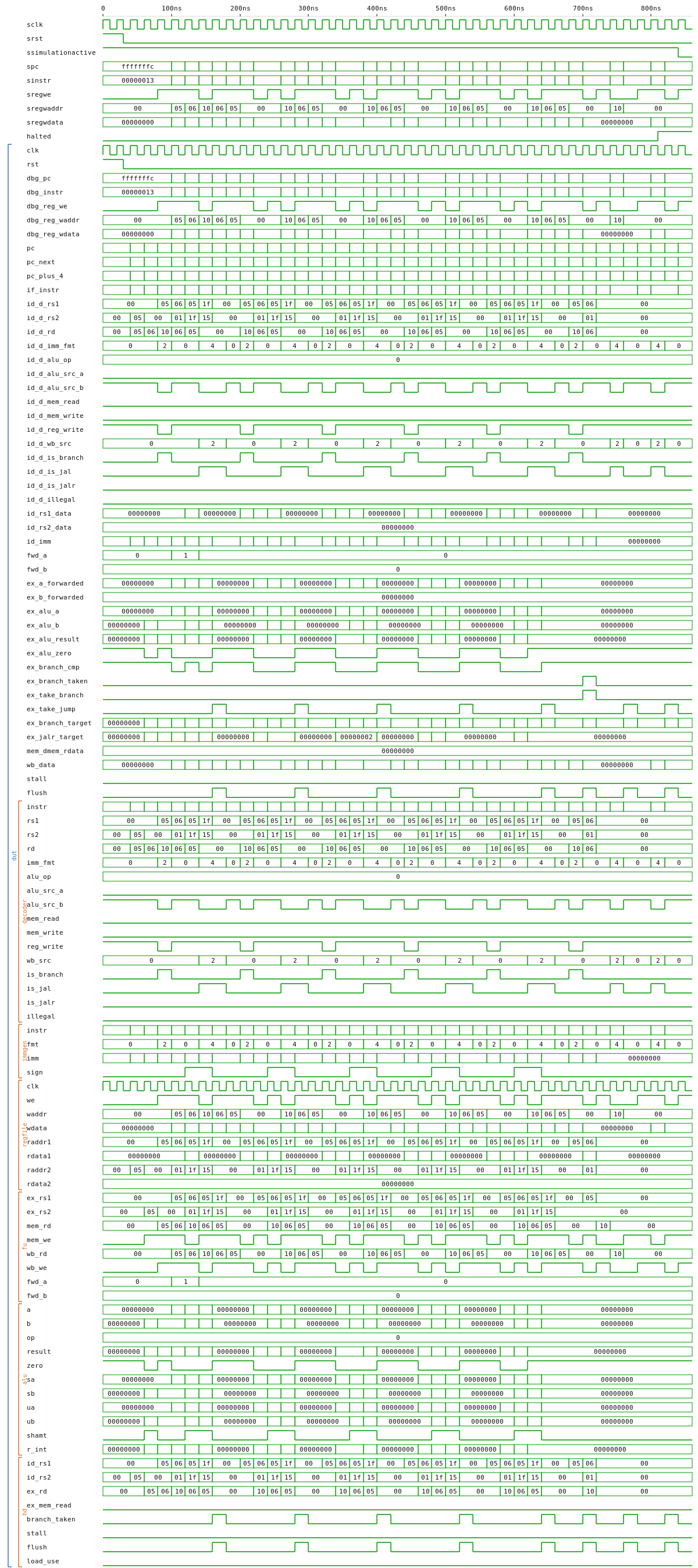
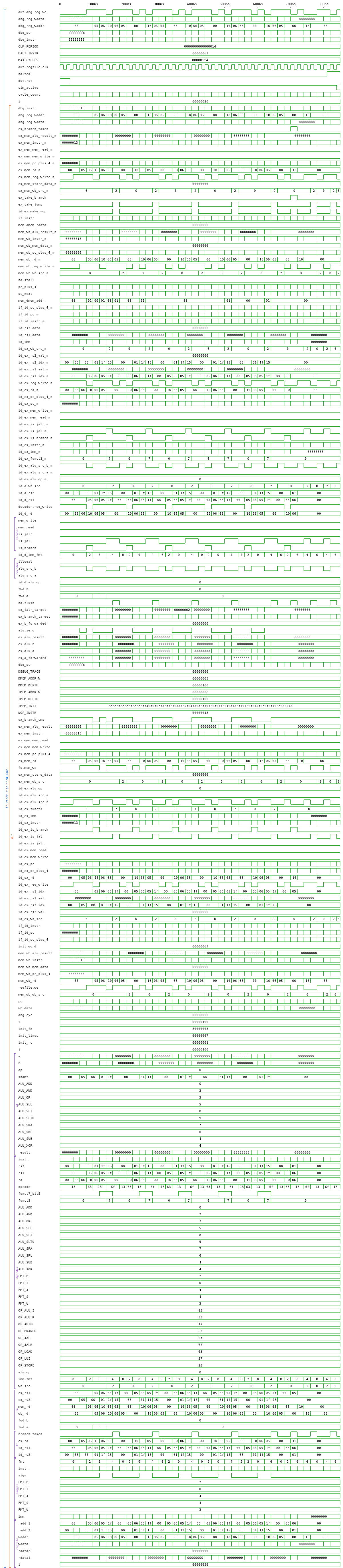
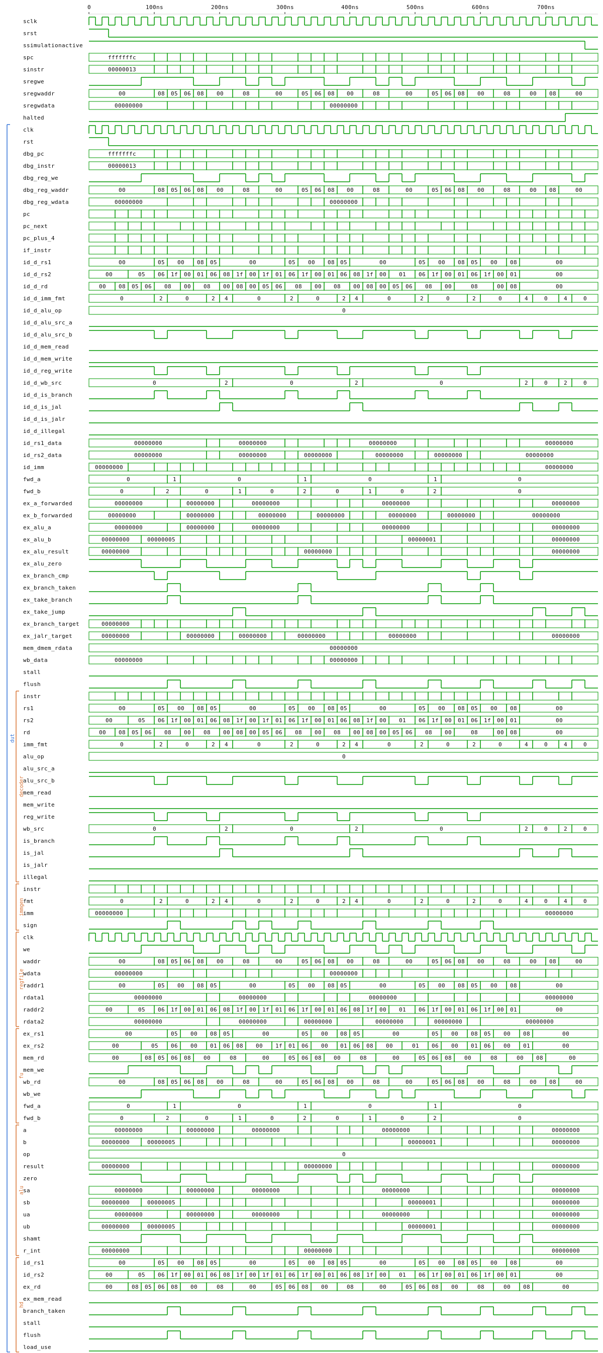
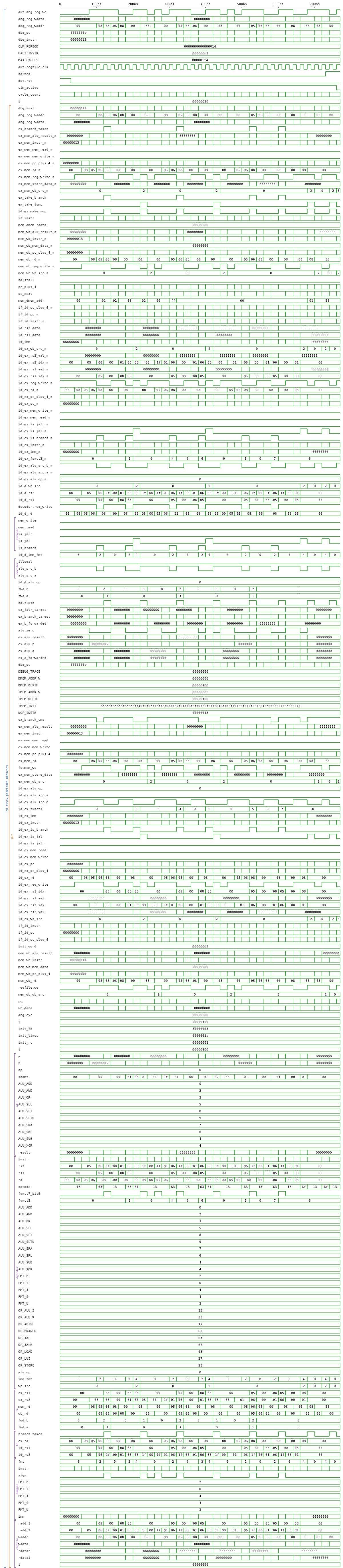
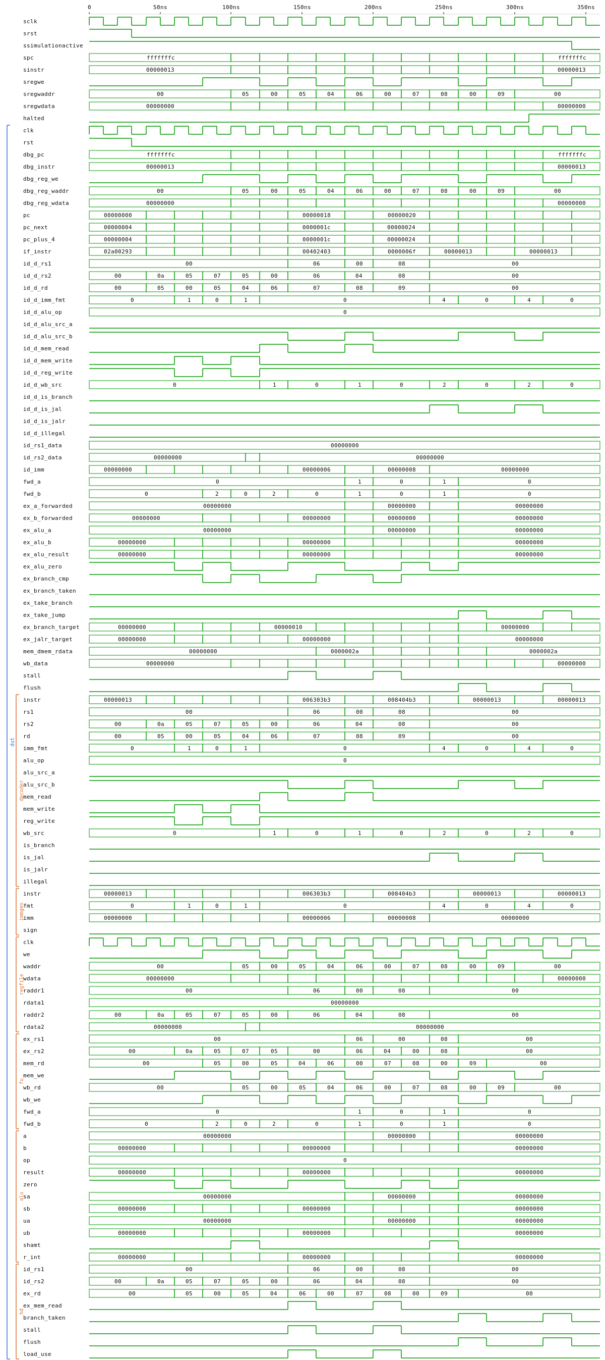
riscv_pipelined — 5-stage IF/ID/EX/MEM/WB pipeline; full forwarding, load-use stall, branch flush
| VHDL | Verilog | |
|---|---|---|
riscv_pipelined (netlist) |
 |
 |
tb_riscv_pipelined_addi |
 |
 |
tb_riscv_pipelined_loop |
 |
 |
tb_riscv_pipelined_branches |
 |
 |
tb_riscv_pipelined_load_use |
 |
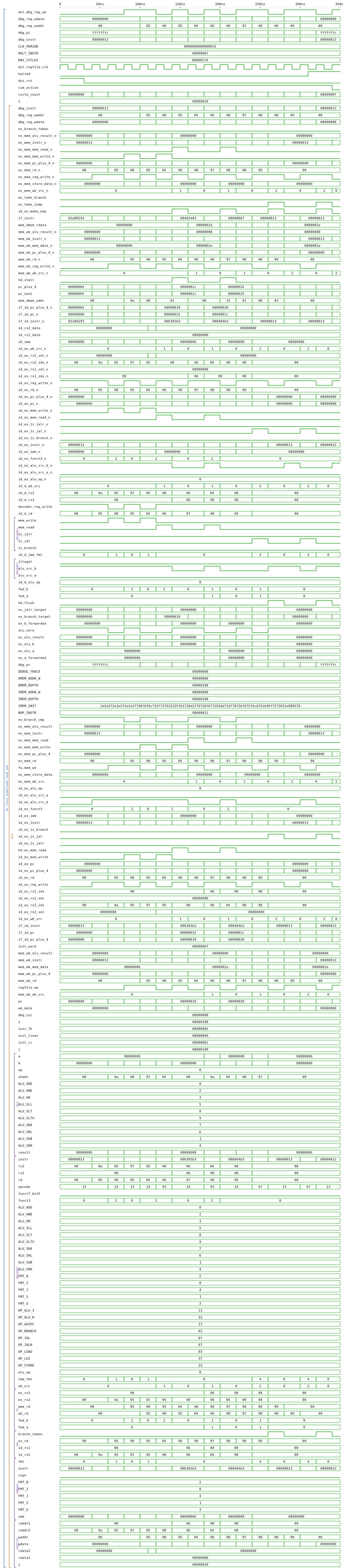 |
Same external port shape as riscv_singlecycle, same hex programs run unchanged — reading the two diagrams side by side shows exactly what pipelining adds: 4 pipeline-register stages, the forwarding_unit muxes at the EX-stage ALU operands, and the hazard_detector driving stall + flush. Adds a fourth TB (tb_riscv_pipelined_load_use) that specifically validates the one-cycle bubble inserted on a load-use hazard.
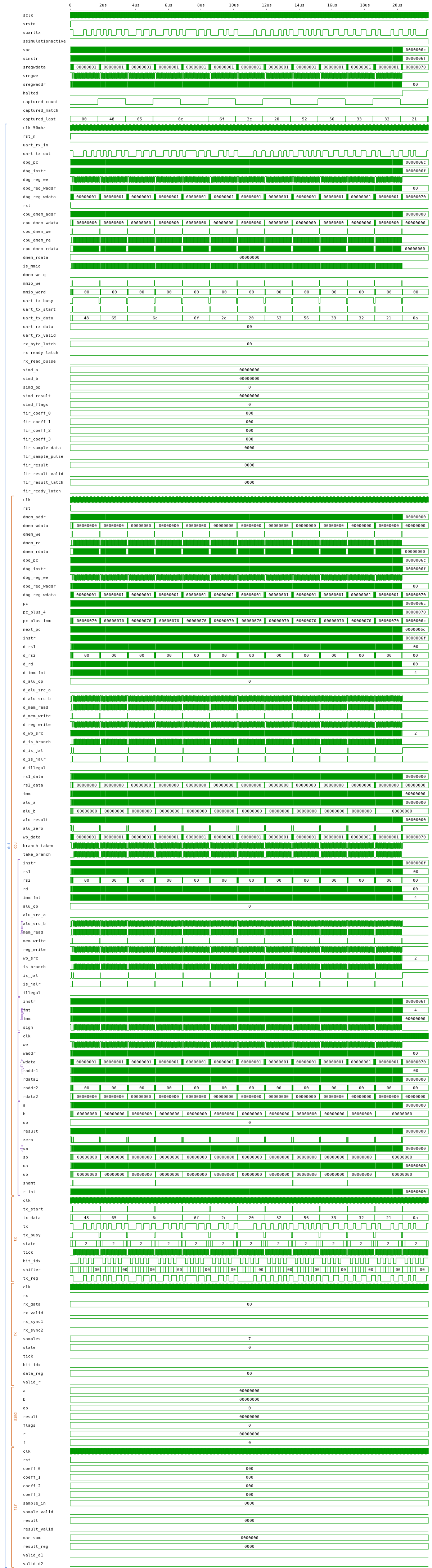
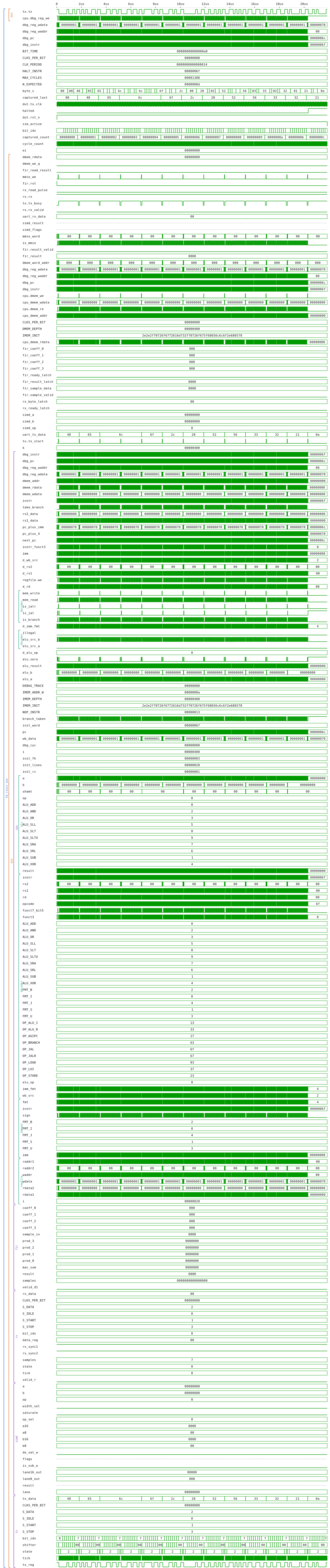
riscv_soc — small SoC: single-cycle CPU + DMEM + UART + SIMD ALU + 4-tap FIR over MMIO
| VHDL | Verilog | |
|---|---|---|
riscv_soc (netlist) |
 |
 |
tb_riscv_soc (Hello-RV32) |
 |
 |
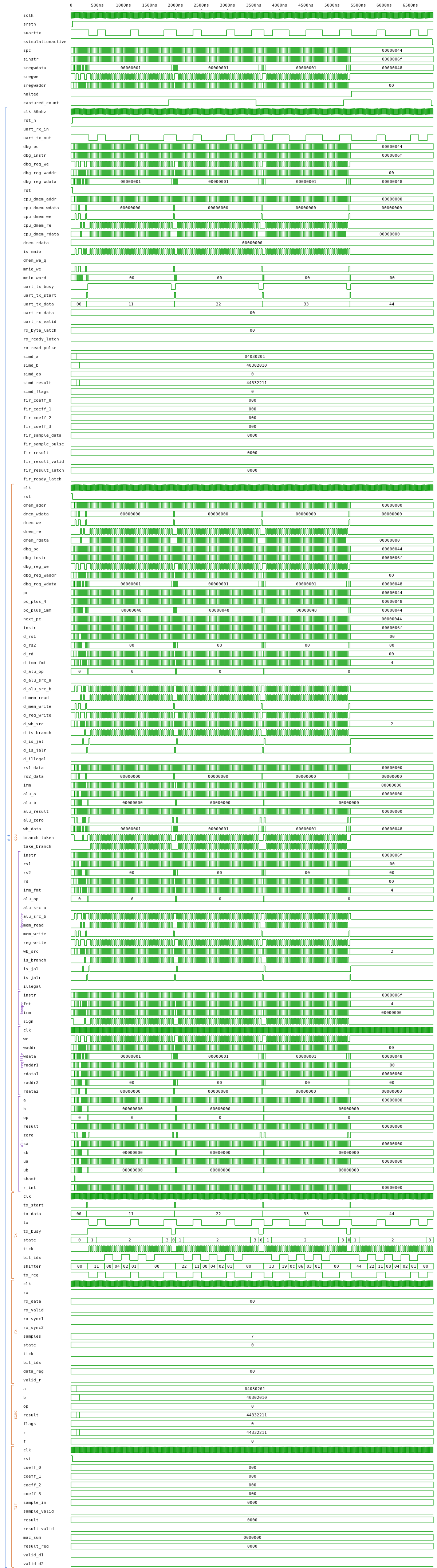
tb_riscv_soc_simd (SIMD demo) |
 |
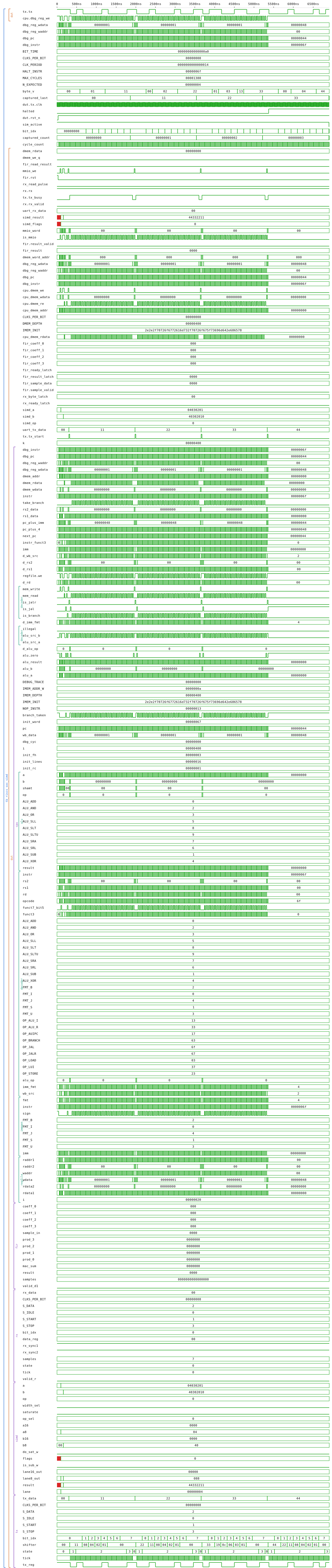 |
The first runnable computer in the repo. The single-cycle CPU drives an MMIO bus that fans out to UART (TX+RX), the simd_alu packed SIMD ALU, the fir4tap FIR filter, and a 4 KB DMEM. Two demo programs: prog_hello prints "Hello, RV32!\n" over UART; prog_simd loads SIMD operands via MMIO, reads the result, streams the 4 bytes over UART. The submodule cells in the diagram are clickable and rendered hierarchically by netlistsvg. See cpu/README.md for the full MMIO address map.
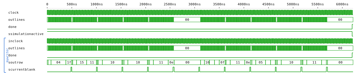
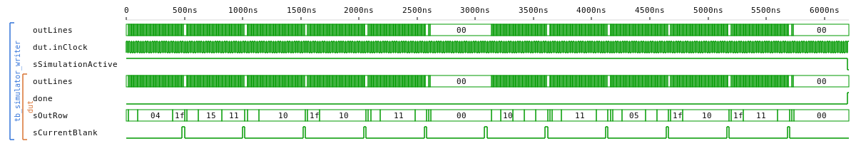
simulator_writer — produces a waveform trace for the simulator flow
| VHDL | Verilog | |
|---|---|---|
tl_simulator_writer (netlist) |
 |
 |
tb_simulator_writer |
 |
 |
A few demos running on the board itself:
| VGA driver (2nd revision) | Scrolling alphanumeric 7-seg |
|---|---|
 |
 |

Every project in this repo builds through one small set of make rules.
Adding a project is two files, zero workflow edits — CI auto-discovers
any Makefile that includes mk/common.mk.
| Stage | Tool chain | Output |
|---|---|---|
| simulate | GHDL (VHDL) / iverilog (Verilog) | build/<tb>.fst |
| diagram | yosys + ghdl-yosys-plugin → netlistsvg | build/<top>.svg |
| waveform | FST → waveview | build/<tb>.svg, build/<tb>.png |
Each matrix job:
- Simulates the VHDL testbench — and the Verilog mirror if present.
- Renders the netlist diagram (both languages).
- Renders the waveform via waveview (SVG + PNG).
- Publishes the
.svg/.pngto the orphanci-gallerybranch (one directory per run,run-<id>/<project>/, plus alatest/pointer refreshed on everymainpush). Those images show up inline in (a) per-job step summaries, (b) the run-summary page, and (c) the auto-upserted PR comment on pull requests.
make                                  # build every project
make -C basics/blink_led simulate     # one project, one stage
make list                             # what CI would discover
make clean                      # nuke every build/
…or through the same container CI uses (ships GHDL, yosys + ghdl-plugin, iverilog, netlistsvg, waveview):
podman run --rm -it -v "$PWD":/work -w /work \
    ghcr.io/naelolaiz/hdltools:release \
    make
Swap podman for docker if that is your local runtime.
The build machinery is bilingual. A project that defines V_TOP /
V_TB_TOPS / V_SRC_FILES / V_TB_FILES in its Makefile also gets a
parallel iverilog / yosys flow whose artifacts share build/ with the
VHDL ones via a _v suffix (build/<top>_v.svg, build/<tb>_v.fst,
build/<tb>_v.png) — both languages coexist without colliding.
| target | tooling |
|---|---|
simulate_v |
iverilog -g2012 → vvp (FST) |
diagram_v |
yosys read_verilog → netlistsvg |
waveform_v |
FST → waveview |
make all runs both flows when both language sets are populated.
Verilog testbenches must call $dumpfile(`FST_OUT) — the Makefile
supplies that define so the dump file always lands in build/, and
runs vvp with IVERILOG_DUMPER=fst so iverilog 13 emits FST. See
blink_led/test/tb_blink_led.v for the
canonical pattern.
See CONTRIBUTING.md. tl;dr: drop a Makefile that
declares TOP / TB_TOPS / SRC_FILES / TB_FILES (and optionally the
V_* equivalents), include ../../mk/common.mk (one extra ../ for
each level deeper your project sits — display/7segments/text/ uses
../../../mk/common.mk), done.
Projects are grouped by intent. Legend: ✅ built in CI · ⏳ pending adoption (dropping a Makefile is all it takes).
| Project | CI | Languages | Notes |
|---|---|---|---|
| glossary | ✅ | VHDL + Verilog | Symbol legend: every primitive on one diagram (gates, muxes, arith, registers) with truth tables and a custom labelled-gate netlistsvg skin. Board top wires a,b to two buttons and shows AND / OR / XOR / XNOR on the four LEDs. |
| logic_styles | ✅ | VHDL + Verilog | Coding-style tutorial: combinational vs. sequential vs. latch with annotated good/bad examples, three register-init strategies side-by-side, the classic incomplete-process latch trap, plus a board top that surfaces the latch holding behaviour onto an LED. |
| blink_led | ✅ | VHDL + Verilog | Hello-world LED toggler in two flavours: blink_led_minimal (1 FF, MSB-of-counter, power-of-two period) and blink_led (2 FF, exactly tunable period via CLOCKS_TO_OVERFLOW). Side-by-side netlist contrast. |
| pwm_led | ✅ | VHDL + Verilog | Brightness via duty-cycle modulation. |
| Project | CI | Languages | Notes |
|---|---|---|---|
| shift_register | ✅ | VHDL + Verilog | Parameterised shift register. |
| fifo_sync | ✅ | VHDL + Verilog | Synchronous FIFO. |
| ram_sync | ✅ | VHDL + Verilog | Generic synchronous BRAM (single-port, parameterised width / depth). Used as IMEM and DMEM in the RV32I CPU + SoC. |
| random_generator | ✅ | VHDL + Verilog | On-chip RNG (neoTRNG VHDL, LFSR Verilog) shown on a 4-digit 7-segment; button[0] freezes value. |
| serial_to_parallel | ✅ | VHDL + Verilog | SIPO shift + snapshot register; thin wrapper around shift_register. |
| debounce | ✅ | VHDL + Verilog | Switch / button debouncer (from nandland.com), with DEBOUNCE_LIMIT generic so testbenches can compress sim time. |
| rom_lut | ✅ | VHDL + Verilog | Same sin(angle)*nibble ROM stored three ways (inline literal, external hex file, math-computed at elaboration); a multi-method TB drives all three in parallel and asserts bit-identical outputs across 2048 addresses. |
| Project | CI | Languages | Notes |
|---|---|---|---|
| 7segments/counter | ✅ | VHDL + Verilog | Multiplexed 4-digit counter. |
| 7segments/text | ✅ | VHDL + Verilog | Scrolling ASCII text on a 4-digit display; button[0] pauses scroll. |
| 7segments/clock | ✅ | VHDL + Verilog | Multiplexed clock with HHMM/MMSS view, blinking dot, alarm. |
| vga_sprites | ✅ | VHDL + Verilog | Rotating VGA sprites (trig LUT) + optional gravity. |
| vga | ✅ | VHDL + Verilog | Bouncing square + scrolling text on a font ROM, with three pause/reset/speed buttons (debounced) and four status LEDs. |
| Project | CI | Languages | Notes |
|---|---|---|---|
| uart_tx | ✅ | VHDL + Verilog | 8N1 UART transmitter. |
| uart_rx | ✅ | VHDL + Verilog | 8N1 UART receiver, 3-tap majority sampler at mid-bit. Pairs with uart_tx; used by cpu/riscv_soc's memory-mapped UART_RX peripheral. |
| i2s_test_1 | ✅ | VHDL + Verilog | Sine NCO over I2S to a PCM5102 DAC; mono + stereo top-levels share one nco_sine / sincos_lut chain. |
| uda1380 | ✅ | VHDL + Verilog | Boot-FSM walks the codec init sequence over I2C; integrated I2S master + tone source for end-to-end playback. Two tops: simulation (inout) + a _core diagram variant with split (oe, i) so netlistsvg renders. |
A tutorial-grade 32-bit RISC-V (RV32I subset) computer built bottom-up from the building blocks above. See cpu/README.md for the recommended reading order, ISA reference, SoC MMIO map, and how to write+assemble+run your own program.
| Project | CI | Languages | Notes |
|---|---|---|---|
| cpu/riscv_singlecycle | ✅ | VHDL + Verilog | Textbook single-cycle RV32I CPU: one instruction per clock, no pipeline. Three test programs (addi / loop / branches) run end-to-end. |
| cpu/riscv_soc | ✅ | VHDL + Verilog | Small SoC around the single-cycle CPU: 4 KB DMEM + memory-mapped UART (TX/RX) + SIMD ALU + 4-tap FIR. prog_hello prints over UART; prog_simd drives the SIMD accelerator end-to-end. |
| cpu/riscv_pipelined | ✅ | VHDL + Verilog | 5-stage IF/ID/EX/MEM/WB pipeline with full forwarding + load-use stall + branch flush. Drop-in replacement for the single-cycle CPU. |
RV32-specific sub-entities that compose into the CPUs above. (Generic blocks like ram_sync live in top-level building_blocks/.)
| Project | CI | Languages | Notes |
|---|---|---|---|
| cpu/building_blocks/regfile_rv32 | ✅ | VHDL + Verilog | 32 × 32 register file; x0 hardwired to 0; falling-edge writes so a same-cycle WB-then-ID read picks up the new value. |
| cpu/building_blocks/alu_rv32 | ✅ | VHDL + Verilog | 10-op ALU (add/sub/and/or/xor/sll/srl/sra/slt/sltu) — covers every R-/I-type RV32I arithmetic case. |
| cpu/building_blocks/immgen_rv32 | ✅ | VHDL + Verilog | Immediate generator for the 5 RV32I encoding formats (I/S/B/U/J), sign-extended. |
| cpu/building_blocks/decoder_rv32 | ✅ | VHDL + Verilog | Combinational decoder driving every control signal: rs1/rs2/rd, alu_op, alu_src_a/b, reg_write, mem_read, mem_write, wb_src, is_branch, is_jal, is_jalr, illegal. |
| cpu/building_blocks/forwarding_unit | ✅ | VHDL + Verilog | Pipeline forwarding-mux decision unit (MEM→EX, WB→EX). Preserves the x0-stays-zero invariant. |
| cpu/building_blocks/hazard_detector | ✅ | VHDL + Verilog | Pipeline stall (load-use) + flush (taken branch) decision unit. |
| cpu/building_blocks/simd_alu | ✅ | VHDL + Verilog | Packed SIMD ALU (4×8 / 2×16 add/sub/min/max + saturation). Hangs off the SoC's MMIO map. |
| cpu/building_blocks/fir4tap | ✅ | VHDL + Verilog | 4-tap streaming FIR using the Cyclone IV hard 9×9 multipliers; Q1.8 coefficients. |
| Project | CI | Languages | Notes |
|---|---|---|---|
| tools/rv32_asm | n/a | Python | Tiny RV32I assembler — converts a .S source (the subset the CPUs implement) to a .hex file the testbenches $readmemh / textio-load. |
| simulator_writer | ✅ | VHDL + Verilog | Waveform writer used to sanity-check the sim flow. |
- Blinking LED (keyboard-driven variant).
- 7-segment driver:
- multiplexed 4-digit counter;
- alphanumeric characters + scrolling strings.
- Rotating sprite driven by a precomputed sin/cos LUT.
- CI: per-project simulate + diagram + waveview waveform, with auto-discovery and a pinned hdltools container. Build machinery merged in from hdltools and fpga_tutorial.
- Every built-in-CI example ships a Verilog twin with matching behaviour — read the two languages side-by-side in Gallery.
- New dual-language examples:
pwm_led,uart_tx,shift_register,fifo_sync.
A bottom-up 32-bit RISC-V (RV32I subset) computer, composed from the project's building blocks. See cpu/README.md for the full tutorial overview.
- CPU building blocks: regfile_rv32, alu_rv32, immgen_rv32, decoder_rv32, forwarding_unit, hazard_detector, simd_alu (packed SIMD), fir4tap (streaming FIR) — all paired VHDL + Verilog with assertion-driven testbenches.
- Tiny assembler (tools/rv32_asm): Python script converting
.S(the subset implemented) into.hexfor$readmemh/ textio load. - Single-cycle CPU (cpu/riscv_singlecycle): classic textbook flat datapath, one instruction per clock.
- Pipelined CPU (cpu/riscv_pipelined): 5-stage IF/ID/EX/MEM/WB with full forwarding, load-use stall, branch flush — drop-in replacement for the single-cycle CPU.
- SoC (cpu/riscv_soc): single-cycle CPU + 4 KB DMEM + memory-mapped UART (TX + RX) + simd_alu + fir4tap. A demo program (
prog_simd.S) drives the SIMD ALU through the bus and streams the 4-byte result over UART, end-to-end. - Documentation: per-block READMEs, plus cpu/README.md with reading order, ISA reference card, SoC MMIO address map, and a "write+assemble+run your own program" walkthrough.
Out of scope by design (deferrable): byte/halfword memory ops, CSRs, interrupts, M-extension, cache, branch prediction.
- Per-project multi-testbench support in
mk/common.mk(TB_TOPS/V_TB_TOPSlists): each testbench produces its own waveform in CI so projects can ship focused unit tests alongside integration ones. - Assertion-driven testbenches instead of stimulus-only: every VHDL and Verilog TB exercises algebraic or cause-effect properties that fail the build on regression, not just waveform eyeballing.
- New testbenches:
vga_sprites/tb_multiply_by_sin_lut(LUT unit tests),vga_sprites/tb_sprite_gravity(gravity cause-effect),fifo_sync/tb_fifo_sync_overlapping(simultaneous read+write invariants). Rewrotedisplay/7segments/counter/tb_counterfrom 0 assertions to three invariants (mux one-hot, valid 7-seg encodings, full digit rotation).
7segments/clock— application-level example composed from smaller entities. Working:- Digit entity + cascaded instances.
- Reusable timer entity driving the first digit.
- Reusable time-counter entity (timer inside) for the digit mux.
- HHMM / MMSS view modes toggled by a button, with debouncer (copied from nandland; replace with own version).
- Set time with +/- buttons; speed scales with the view mode.
- Blink the middle dot —
DotBlinkerentity, 1 Hz in MMSS, half-rate in HHMM. Cause-effect TB asserts the 2:1 ratio. - Alarm — second
Digitcascade for the alarm time, view-toggle button oninputButtons(1), intermittent ~400 Hz buzzer through the newAlarmTriggerentity. TB covers all four match/mismatch × tone/gate combinations and the immediate transition to '0' when the match breaks. - Project is CI-compatible:
Makefilediscovered by the top-level orchestrator, ghdl--std=08fixes applied ('HIGHon integers, slicing of type-conversions), both VHDL and Verilog netlists synthesise (noSKIP_DIAGRAM), waveforms rendered for all four testbenches. - Full Verilog mirror — every leaf entity (
Timer,VariableTimer,CounterTimer,Debounce,Digit,DotBlinker,AlarmTrigger) plus the top-leveltop_level_7segments_clockships a Verilog twin with identical- shape testbenches.
- Remaining:
- Milliseconds view.
- Dynamic speed for set-time UX.
- Drop redundant timers; general cleanup.
- Interrupt-service-routine (ISR) support for the RISC-V CPU: a
minimal CSR file (
mtvec,mepc,mcause,mstatus), an external-interrupt pin, and themretinstruction so a program can install a handler and resume. The MMIO peripherals (UART_RX, buttons, ...) become real interrupt sources rather than polled-only devices. - Small game using the buttons + 7-segment display (snake / space
invaders). On-FPGA RNG is now available via
random_generator. - Adapt the 7-seg examples (clock, game, …) to render on VGA, reusing
the glyph-ROM text renderer the
vgaexample already ships (Pixel_On_Text+Font_Rom). - I²S driver + an FFT implementation → spectral analyser (I²S → FFT → VGA). Eventually extend with IFFT / DSP kernels for a small FX module; later BLE / Bluetooth audio.
- projectf.io tutorials · recommended FPGA sites · how-to guides
- FPGA designs with VHDL
- Compatible projects for the same board: